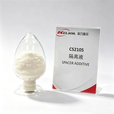

Drilling through high-salt formations, evaporite intercalations, and massive salt-dome structures presents some of the most daunting technical challenges in modern oilfield completion chemistry. These subterranean environments, frequently saturated with sodium chloride (NaCl), calcium chloride (CaCl2), or magnesium chloride (MgCl2), severely disrupt the hydration kinetics of standard oil well cement. When an unadjusted cement slurry contacts these aggressive high-salt zones, it often undergoes rapid chemical degradation, culminating in premature slurry gelation or catastrophic flash setting. Slurry gelation causes an uncontrollable spike in dynamic viscosity and gel strength before the designated thickening time is reached, while flash setting leads to instantaneous, irreversible hardening. Both phenomena compromise well integrity, plug up casing strings, and lead to disastrous financial losses due to remedial squeezing operations.
To successfully mitigate the risks of chemical flash setting and uncontrolled fluid loss in salt-bed formations, cementing engineers must deeply understand the complex electrolyte interactions occurring within the cement matrix. Securing an optimal slurry design requires moving away from generic chemical combinations and adopting targeted, salt-tolerant additives that maintain stable, predictable thickening curves. Furthermore, testing these designs demands advanced, API-compliant laboratory hardware that can flawlessly simulate dynamic downhole conditions. This technical guide explores the exact chemical mechanisms behind salt-induced cement failures, provides proven material design methodologies, and outlines a comprehensive engineering checklist to ensure flawless execution in high-salt well cementing environments.
The Chemical Mechanisms of Salt-Induced Cement Failures
The effect of salts on oil well cement hydration is highly dualistic, acting as either a beneficial accelerator or a highly destructive destabilizer depending entirely on the concentration and composition of the dissolved brine. At low concentrations (typically 1% to 5% by weight of water), sodium chloride acts as a mild acceleration agent, safely shortening the thickening time. However, when a slurry enters massive evaporite formations or comes into contact with saturated salt water, the overwhelming abundance of electrolytes completely destabilizes the chemical balance of the slurry.
1. Destabilization of Mineral Hydration Kinetics
High-salt concentrations drastically alter the dissolution and precipitation rates of the core mineral phases of oil well cement, particularly tricalcium silicate (C3S) and tricalcium aluminate (C3A). In a saturated brine environment, the high ionic strength forces an explosive, premature hydration of the C3A phase. This uncontrolled reaction rapidly forms extensive networks of interlocking ettringite crystals long before the designated placement time. This structural crystallization causes the cement slurry to lose its fluid properties prematurely, manifesting as severe flash setting or an unpumpable dynamic gelation state.
2. Destruction of Standard Polymer Chains
Traditional, low-tier cementing additives-such as standard fluid loss additives or conventional retarders-rely on fully extended polymer chains to provide viscosity control and water-retention properties. When exposed to high salinity, the dense concentration of positive ions (such as Na+, Ca2+, and Mg2+) shields the negative charges along the anionic polymer backbone. This ionic shielding causes the polymer chains to violently coil, collapse, or precipitate completely out of solution. Once the polymer matrix collapses, the slurry suffers from extreme, immediate fluid loss into the formation, resulting in rapid dehydration, localized bridging, and subsequent flash setting.
Technical Characteristics of Salt-Tolerant Slurry Systems
Overcoming the chemical challenges of evaporite zones requires shifting toward advanced, salt-resistant cementing additives. Modern slurry architectures utilize highly specialized copolymers that resist electrolyte degradation and maintain their structural integrity even in saturated brine environments.
The engineering table below contrasts the technical behavioral characteristics of traditional additive packages with advanced, salt-resistant chemical technologies in high-salinity zones:
| Slurry Performance Vector | Traditional Cementing Additive Package | Advanced Salt-Resistant Chemical Technology |
|---|---|---|
| Polymer Chain Stability | Prone to severe coiling, charge shielding, and chemical precipitation in saturated NaCl/MgCl2 brine. | AMPS-based copolymers maintain extended chain structures and resist electrolyte shielding. |
| Thickening Time Profile | Unpredictable, exhibiting sudden consistency spikes (Bc) and a high risk of flash setting. | Linear, highly predictable thickening curves with a sharp, well-defined right-angle set. |
| Fluid Loss Control Integrity | Degrades rapidly, with API fluid loss values frequently spiking well above 200 mL under high salinity. | Excellent water retention, consistently maintaining strict API fluid loss control below 50 mL. |
| Rheological Rheology | High initial plastic viscosity, prone to severe static gelation and excessive yield values. | Low, stable plastic viscosity with optimized flow properties for effortless primary displacement. |
The deployment of advanced 2-Acrylamido-2-methylpropane sulfonic acid (AMPS) grafted copolymers serves as the industry baseline for handling extreme salinity. The bulky, highly hydrophilic sulfonic acid groups on the AMPS monomer are exceptionally resistant to ionic shielding. This chemical architecture allows the polymer to remain fully extended in saturated brine, enabling it to efficiently block the micro-pores within the cement filter cake. Consequently, utilizing an AMPS-based fluid loss additive guarantees that the slurry maintains strict fluid loss control, prevents localized water depletion, and successfully eliminates the environmental conditions that catalyze premature slurry gelation.
Engineering Strategies for Reliable High-Salt Cementing
Formulating a high-performance slurry for salt-dome applications requires a highly focused chemical strategy. First, engineers must ensure the cement mix water is pre-hydrated or deliberately salted to achieve chemical equilibrium with the formation. Mixing a fresh-water slurry and pumping it into a massive halite zone causes the cement to actively dissolve the surrounding salt rock during displacement. This uncontrolled dissolution creates large structural voids, destroys the interfacial bonding profile, and leads to severe zonal isolation failures. By utilizing salt-saturated mix water, the slurry is chemically passivated, preventing further washout of the salt formation.
Second, the selection of the cement retarder must complement the salt-tolerant fluid loss additive. High-performance AMPS-compatible retarders work synergistically with the polymer matrix to delay the hydration of C3S and C3A phases uniformly. This targeted chemical retardation prevents any premature consistency buildup (Bc) in the high-pressure, high-temperature (HPHT) consistometer, ensuring the slurry maintains a low, pumpable viscosity throughout the entire placement window. Furthermore, utilizing comprehensive B2B manufacturer support provides laboratories with precise additive equivalence mappings and custom chemical dosages tailored to exact wellbore salinity profiles, maximizing economic efficiency without overdesigning the slurry system.
Checklist: Preventing Slurry Gelation and Flash Setting
Use this comprehensive laboratory and operational engineering checklist to rigorously evaluate your cement slurry designs and safeguard well integrity across highly volatile, high-salt formations.
✔ Step 1: Characterize Formation Brine and Core Salinity Profiles
- Analyze downhole fluid samples or log data to determine the exact concentrations of NaCl, CaCl2, and MgCl2 present within the targeting formation zones.
- Determine if the salt formation is prone to creep or dissolution, and calculate the required salt saturation percentage for the mix water to establish chemical equilibrium.
- Ensure that source water used in the laboratory for batch testing matches the exact chemical composition and ionic strength of the water supply designated for field mixing.
✔ Step 2: Formulate with Highly Specialized Salt-Tolerant Additives
- Eliminate standard, non-modified cellulose or generic polymers that are vulnerable to charge shielding and coiling in the presence of aggressive electrolytes.
- Incorporate high-performance, AMPS-based fluid loss additives specifically engineered to maintain structural elongation and water-retention properties in high-salinity brines.
- Select specialized cement retarders that work synergistically with salt-saturated systems, ensuring they do not trigger premature slurry gelation or erratic consistency spikes at elevated temperatures.
✔ Step 3: Execute High-Precision Laboratory Mixing Protocols
- Utilize an API-compliant, constant speed mixer equipped with precise microprocessor controls to ensure uniform energy distribution during slurry preparation.
- Follow strict API Spec 10A/10B mixing schedules, strictly avoiding manual or non-standard mixing methods that can alter the initial hydration kinetics and mask flash-setting tendencies.
- Visually inspect the newly mixed slurry for any early indications of surface gelation, high yield stress, or severe air entrainment before transferring it to testing cells.
✔ Step 4: Validate Performance via Advanced HPHT Testing Instrumentation
- Run comprehensive thickening time tests on an advanced HPHT consistometer equipped with smart PLC intelligent control systems to guarantee precise temperature and pressure ramp schedules.
- Verify that the resulting thickening curve shows a flat, stable consistency profile below 30 Bc for the duration of the pumping window, followed by a sharp right-angle set.
- Perform static gel strength (SGS) testing to map the zero-gel time and transition period, ensuring the slurry does not develop a prolonged, dangerous static gel strength profile that allows gas migration.
- Conduct high-pressure fluid loss tests at the exact simulated bottom-hole circulating temperature (BHCT) to confirm the API fluid loss value remains securely below 50 mL.
✔ Step 5: Implement Quality Assurance and Multi-Stage Safety Systems
- Verify that all laboratory testing instruments comply strictly with API 10A and API 10B standards and are manufactured under certified ISO9001 and HSE management frameworks.
- Confirm that the automated testing systems feature active digital software alarms and multi-stage cutoffs to handle unexpected over-pressure or over-temperature events safely.
- Ensure that your equipment supplier provides readily available standardized spare parts, high-wear consumables, and reliable technical support to eliminate laboratory testing delays.
Conclusion
Successfully cementing high-salt formations requires a flawless combination of advanced polymer chemistry and highly precise laboratory testing protocols. Mitigating the severe operational risks of slurry gelation and premature flash setting demands a transition away from standard, salt-sensitive additives toward robust, AMPS-based copolymer architectures that resist electrolyte degradation. By executing rigorous testing schedules on API-compliant HPHT consistometers and automated fluid loss cells, cementing engineers can precisely verify slurry behavior under simulated downhole conditions. This meticulous engineering approach guarantees predictable thickening times, superior fluid loss control, and tight zonal isolation, safeguarding structural well integrity across the most hostile evaporite environments.