
When petroleum drilling and completions engineers investigate what is cementing in oil and gas, they define it as the critical well construction process of mixing hydraulic Portland cement, mix water, and specialized chemical additives into a homogenous slurry and pumping it down casing strings to displace drilling fluid into the annular space between steel pipe and geological formations across complex energy frontiers in the Middle East, the Gulf of Mexico, and deepwater basins. Exploring what is cementing in oil and gas reveals that cementing serves as an irreversible barrier system engineered to achieve permanent hydraulic zonal isolation, support the structural weight of casing strings, protect steel pipe from corrosive hydrogen sulfide (H₂S) and carbon dioxide (CO₂) brines, and reinforce weak borehole formations against tectonic collapse. By mastering what is cementing in oil and gas under API Spec 10A and API RP 10B-2 standards, operators optimize slurry rheology, prevent gas channeling, eliminate equivalent circulating density (ECD) surges, and safeguard multidecade well integrity.

The Operational Significance of Wellbore Cementing in Modern Energy Extraction
In petroleum exploration and hydrocarbon production, drilling creates an open cylindrical pathway through heterogeneous subterranean strata. This drilled borehole penetrates various geological horizons, including porous freshwater aquifers, reactive sloughing shales, unconsolidated sandstone intervals, overpressured gas caps, and fractured carbonate formations. Without an impermeable mechanical barrier to seal this void, subterranean fluids would flow uncontrolled between porous zones, cross-contaminating drinking water reserves, destroying reservoir drive mechanisms, and inducing catastrophic surface blowouts.
Cementing represents the definitive engineering solution that converts an open hole into a safe, pressure-contained subterranean conduit. Once casing strings-heavy steel pipes assembled section by section-are lowered into the drilled hole, cement slurry is mixed on surface batching units and pumped through the casing shoe, turning 180 degrees to ascend into the annular void. As the slurry cures, hydration reactions transform the viscous liquid suspension into a stone sheath possessing high compressive and shear bond strength.
Because primary cementing cannot be physically excavated or redone without expensive mechanical milling and squeeze operations, its initial design must achieve zero defect margins. Investigating what is cementing in oil and gas demonstrates how advanced chemical design, fluid displacement dynamics, and downhole rheological control work in synergy. Incorporating specialized fluid loss additives, high-temperature retarders, dispersants, and anti-gas migration agents ensures that the cement slurry remains pumpable during placement, displaces drilling mud efficiently, and develops an impermeable barrier that withstands production stresses throughout the well's productive life.
1. Defining What Cementing Means in Oil and Gas Engineering
To thoroughly understand what is cementing in oil and gas, engineers evaluate the process as a composite materials science discipline that integrates chemical engineering, hydraulic fluid mechanics, and structural mechanics. Oilwell cementing utilizes specialized hydraulic cements-primarily API Class A, Class C, Class G, and Class H formulations. Unlike standard construction concretes, oilwell slurries contain finely ground clinker minerals mixed with specific water-to-cement ratios (typically 0.38 to 0.46) without coarse gravel aggregates, ensuring smooth laminar pumpability through restricted annular clearances.
The functional success of well cementing depends on chemical admixtures known as cementing additives. Base Portland cement mixed with water at elevated downhole temperatures hydrates within minutes. By introducing synthetic 2-acrylamido-2-methylpropane sulfonic acid (AMPS) polymers, modified lignosulfonates, and cellulose ethers, chemists tailor the slurry's thickening time, control water filtrate invasion into permeable rock, and optimize rheological yield points. Once placed, the cement sheath forms a continuous rock barrier that seals the casing-formation interface.
2. Core Objectives and Purposes of Wellbore Cementing
Primary cementing serves several interconnected technical objectives that are essential for long-term wellbore stability and production:
Formation Zonal Isolation
The primary objective of cementing is to establish hydraulic isolation across permeable strata. Subsurface rock formations contain oil, natural gas, and saline water under varying pressure regimes. An impermeable cement sheath prevents inter-zonal cross-flow, protects shallow freshwater aquifers from hydrocarbon contamination, and stops water-bearing formations from invading producing oil horizons.
Mechanical Casing Support and Corrosion Protection
Deep casing strings weigh hundreds of tons. The set cement sheath bonds firmly to both the outer surface of casing steel and the rock face, distributing structural weight and preventing pipe buckling under axial compression. Furthermore, the alkaline chemical environment of the set cement matrix (pH > 12) passivates steel, shielding tubulars from corrosive subterranean brines containing H₂S and CO₂.
Wellbore Mechanical Reinforcement
Drilling through unconsolidated sands, micro-fractured shales, and tectonically stressed fault zones can destabilize borehole walls. The cement sheath reinforces the rock, sealing micro-fissures and preventing formation washouts, shale sloughing, and hole collapse during subsequent drilling of deeper sections.
Hydraulic Foundation for Perforation and Stimulation
Completing a well requires firing explosive shaped charges through casing and cement into the pay zone, followed by hydraulic fracturing treatments at pressures exceeding 70 to 100 MPa (10,000 to 14,500 psi). A resilient cement sheath confines treatment pressures to the target interval, preventing fracturing fluids from breaking into adjacent water zones.

Technical Evaluation: Cementing Objectives vs. Downhole Failure Risks
To highlight the critical role of chemical admixtures during well construction, the table below compares primary cementing objectives with downhole risks that occur when slurry design is un-optimized:
3. The Four-Stage Primary Cementing Process Workflow
Executing a well cementing job requires a structured, multidisciplinary operational sequence. The field cementing process comprises four primary operational stages:
Stage 1: Pre-Cementing Wellbore Conditioning and Hydraulics Optimization
Prior to pumping cement, drilling fluid is circulated through the casing string for multiple hole volumes to break gel strength, cool downhole temperatures, and sweep out residual drill cuttings. Chemical washes containing surfactants and weighted mud spacers are pumped ahead of the cement. The spacer must possess a density intermediate between the drilling mud and cement slurry, creating an effective rheological barrier that cleans casing walls without triggering formation lost circulation.
Stage 2: Primary Slurry Mixing and Wiper Plug Displacement
On the rig floor, a bottom cementing plug with a rupturable diaphragm is released ahead of the cement slurry. The slurry is mixed using automated recirculating mixers that maintain bulk density within ±0.01 g/cm³. Once the calculated volume is pumped, a solid top wiper plug is loaded into the cementing head. High-pressure drilling fluid is pumped behind the top plug, displacing the slurry down the casing. When the bottom plug lands on the float collar, differential pressure ruptures its diaphragm, allowing cement to turn the corner and enter the annulus. Pumping continues until the top plug lands firmly on the float collar ("plug bump"), confirming complete displacement.
Stage 3: Multi-Stage Cementing Operations (When Required)
In deep wells with extended casing intervals or formations with low fracture breakdown gradients, pumping a continuous cement column can generate excessive hydrostatic pressure, fracturing weak zones. In these applications, a stage cementing collar (DV tool) is integrated into the casing string. The lower interval is cemented first (Stage 1), after which an internal sleeve is hydraulically opened to circulate a second stage (Stage 2) of cement across upper formations, ensuring complete annular coverage without exceeding fracture gradients.
Stage 4: Post-Job Evaluation and Acoustic Zonal Verification
After waiting-on-cement (WOC) protocols allow the slurry to develop regulatory compressive strength (typically >500 to 1,500 psi), wireline logging tools are deployed. Radial Cement Bond Logs (CBL) and Variable Density Logs (VDL), alongside ultrasonic pulse-echo imaging tools, evaluate acoustic attenuation across the casing circumference. These logs detect micro-annuli, channel voids, or uncontaminated mud films, confirming that the cement sheath forms a continuous hydraulic seal.

4. The First Stage of Cementing: Criticality of Primary Zonal Sealing
The first stage of cementing-widely termed primary cementing-is the most critical phase of the entire well construction process. It focuses on isolating the lowest section of the wellbore, where casing tubulars intersect the target hydrocarbon pay zones and adjacent overpressured formations.
Operating in this deep interval requires tight chemical control. Because temperatures and pressures are at their peak, chemical additives must maintain exact water balance and pumpability. High-efficiency fluid loss additives form an impermeable polymer-mineral filter cake across porous reservoir faces, keeping API filtration loss strictly below 35 mL/30 min. Concurrently, high-temperature retarders stabilize Bearden consistency, ensuring that the slurry remains pumpable throughout displacement while transitioning rapidly from 30 Bc to 100 Bc once static. This right-angle setting profile shortens the static gel strength transition window, preventing reservoir gas from permeating the setting matrix and guaranteeing barrier integrity.
Regional Application Case: Deep Carbonate Sour Gas Production Liner Cementing in the Ahwaz Field, Khuzestan Province, Iran
Case Application: Ahwaz Oilfield, Khuzestan Province, Southwestern Iran

Target Formation: Deep HPHT Khami Sour Gas Carbonates (High Pressure, High H₂S & Narrow ECD Window)
Regional Cementing Background in Khuzestan Carbonate Plays
In the Ahwaz field of southwestern Iran, drilling operations penetrate overpressured gas-bearing carbonate reservoirs within the Cretaceous-Jurassic Khami Group. Well measured depths regularly exceed 4,900 to 5,300 meters (16,000 to 17,400 feet). Downhole conditions are severe: bottom-hole static temperatures (BHST) climb to 165°C to 175°C (329°F to 347°F) with formation pressures exceeding 12,000 psi (82.7 MPa). The formations produce sour gas containing H₂S (up to 6%) and CO₂ (up to 8%). Cementing 7-inch production liners across the Khami interval requires heavy Class G slurry systems (1.98 to 2.10 g/cm³) weighted with barite and stabilized by high-temperature polymers.
Regional Cementing Challenges in Extreme HPHT Formations
Operators cementing deep production liners across the Khami formation encounter critical technical hurdles:
- Severe Retarder Sensitivity: At temperatures above 160°C, minor variations of 0.05% BWOC in chemical retarder concentration cause large swings in thickening time, risking premature flash setting or multi-day setting delays.
- Narrow Equivalent Circulating Density (ECD) Windows: Close margins between formation pore pressure and fracture breakdown pressure demand low-viscosity slurries that maintain steady rheology without premature gelation spikes.
- Risk of Sour Gas Channeling: An extended transition time during slurry phase changes allows sour gas invasion into the decaying hydrostatic column, creating sustained casing pressure (SCP).
Technical Requirements for Slurry Qualification
To qualify a heavy 1.98 g/cm³ (16.5 ppg) Class G cement system across the Khami gas zone, the operator established strict performance criteria:
- Thickening time validation on an HPHT consistometer confirming a pumpability window of 5 hours and 30 minutes to 70 Bc under simulated dynamic ramp schedules.
- API fluid loss control strictly below 35 mL/30 min at 165°C using an automated high-temperature stirred fluid loss cell to prevent dehydration.
- Static gel strength (SGS) transition window (from 100 to 500 lbf/100 ft²) of less than 30 minutes, with 24-hour compressive strength exceeding 3,500 psi (24.1 MPa).
How Advanced Primary Cementing Technology Resolved the Field Challenge
Addressing these deepwell operational constraints required applying an exact engineering understanding of what is cementing in oil and gas. During preliminary testing for Well Ahwaz-412, conventional slurry designs suffered severe high-temperature degradation: fluid loss exceeded 180 mL/30 min, and lignosulfonate retarders decomposed, causing slurry gelation in under 2 hours.
The operator's central engineering team re-engineered the primary cement system using KELIOIL synthetic AMPS-based high-temperature retarders (0.85% BWOC) paired with KELIOIL salt-resistant fluid loss additives (1.8% BWOC), sulfonated dispersants, and 35% BWOC silica flour to prevent high-temperature compressive strength retrogression. The AMPS polymers formed a micro-impermeable filter cake that kept API filtration loss at 32 mL/30 min under 165°C and 1,000 psi differential pressure. Dynamic consistometer testing confirmed an ideal right-angle set profile, maintaining a baseline consistency of 18 Bc for 4 hours and 30 minutes before rising cleanly to 70 Bc at 5 hours and 38 minutes. Ultrasonic testing on a UCA verified that the slurry developed 500 psi compressive strength in 9 hours and surpassed 3,850 psi at 24 hours.
During field execution, the slurry placed smoothly across the 1,050-meter liner without surface pressure anomalies or ECD surges. Post-job radial acoustic cement bond logs (CBL-VDL) confirmed 100% circumferential bonding across the Khami sour gas pay zone. Subsequent negative pressure testing recorded zero sustained annular casing pressure, proving that establishing what is cementing in oil and gas through advanced chemical engineering provides the empirical precision required to eliminate cementing failures in extreme HPHT plays.
Standardized Laboratory Testing and API RP 10B-2 Quality Protocols
Achieving field reliability requires confirming slurry behavior through rigorous laboratory protocols adhering to API RP 10B-2 standards:
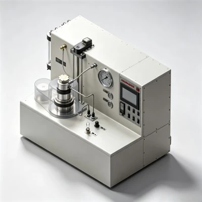
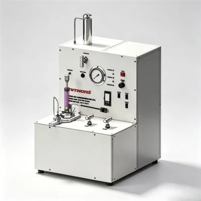
- Consistometer Thickening Time Profiling: Measure thickening time on pressurized HPHT consistometers under simulated geothermal temperature and pressure ramp schedules. The pumpability safety buffer must equal placement duration plus 90 to 120 minutes.
- HPHT Stirred Fluid Loss Testing: Measure filtration under 1,000 psi differential nitrogen pressure across a certified 325-mesh screen at bottom-hole circulating temperature (BHCT). Gas-tight liners require filtration loss below 35 mL/30 min.
- Rotational Rheology Verification: Evaluate plastic viscosity and yield point on rotational viscometers across 600, 300, 200, 100, 6, and 3 rpm. Verify that the fluid maintains laminar displacement properties without inducing ECD surges.
- Free Fluid and Sedimentation Checks: Conditioned slurry poured into an undisturbed 250 mL glass cylinder must show 0.0% free fluid breakout for gas-bearing or deviated wellbores to prevent high-side water channeling.
Frequently Asked Questions (FAQ) Regarding Oil and Gas Well Cementing
1. Why is drilling mud removal essential to successful well cementing?
Cement will not bond to casing steel or formation rock coated with drilling mud. Residual mud films form continuous micro-channels along the annulus, creating pathways for gas and water migration. Pumping engineered chemical washes and weighted mud spacers ahead of cement ensures 100% displacement efficiency and strong acoustic bonding.
2. What is the difference between primary and remedial cementing?
Primary cementing is the initial placement of cement slurry immediately after casing is run into a freshly drilled borehole. Remedial cementing (such as squeeze cementing or setting balanced plug kick-offs) is corrective work performed to repair casing leaks, isolate unwanted water production, or fix poor initial bond quality.
3. Why is silica flour added to cements operating above 110°C (230°F)?
At temperatures exceeding 110°C, the primary binding phase of Portland cement (C-S-H gel) transforms into crystalline alpha-dicalcium silicate hydrate (α-C₂S-H). This phase change causes volumetric shrinkage, increases permeability, and causes compressive strength retrogression. Adding 30% to 40% BWOC silica flour promotes the formation of tobermorite and xonotlite, preserving high mechanical strength.
Strategic Recommendations for Slurry Placement and Well Integrity
In modern energy development, achieving multidecade well integrity depends directly on understanding what is cementing in oil and gas. Combining proper hydraulic displacement design with specialized chemical additives eliminates downhole flash setting, prevents formation fracturing from pressure surges, and establishes an impermeable barrier that protects producing assets.
KELIOIL remains committed to manufacturing high-performance oilfield cementing additives under strict ISO 9001 and API Spec 10A quality control standards. By integrating advanced synthetic polymer chemistry with comprehensive laboratory testing support, KELIOIL empowers operating companies and service contractors worldwide to optimize chemical additive packages, eliminate downhole cementing failures, and ensure life-of-well asset integrity.
Optimize Your Wellbore Cementing Formulations with KELIOIL Additives
Our technical chemical specialists provide customized slurry formulation designs, API Spec 10A laboratory testing verification, and reliable bulk chemical supply of premium cementing additives tailored to demanding onshore and offshore drilling operations.