
When petroleum drilling engineers and completions specialists analyze what is the process of cementing, they define it as an engineered sequence comprising slurry formulation design, borehole mud conditioning, mechanical wiper plug displacement, chemical hydration under downhole thermal regimes, and acoustic bond evaluation across complex energy plays in the Middle East, the Gulf of Mexico, and deepwater basins. Exploring what is the process of cementing reveals that successfully transforming dry Portland cement and chemical additives into an impermeable rock sheath requires precise annular hydraulics, controlled equivalent circulating density (ECD), and complete displacement of drilling fluids from the casing-rock interface. By establishing operational protocols centered on what is the process of cementing under API Spec 10A and API RP 10B-2 testing standards, operators eliminate premature flash setting, prevent subterranean gas channeling during phase transitions, protect freshwater aquifers from cross-flow, and establish lifelong wellbore barrier integrity.

The Operational Significance of the Cementing Process in Hydrocarbon Wells
In petroleum exploration and production, drilling a wellbore creates an open cylindrical conduit across heterogeneous subterranean strata. This drilled passage intersects multiple permeable geological formations containing hydrocarbons, high-salinity brines, and potable groundwater reserves under disparate pore pressure gradients. Without an engineered mechanical and hydraulic seal, formation fluids would migrate freely along the borehole annulus, causing catastrophic subsurface cross-contamination, reservoir pressure depletion, and high-risk surface blowouts.
Cementing represents the definitive engineering intervention that secures the steel casing string within the drilled hole, transforming an open wellbore into a pressure-tight production asset. The operation is complex and inherently irreversible: once the slurry is displaced into the annular space and begins hydration, it cannot be physically retrieved or re-pumped. Any mechanical breakdown, improper mud displacement, or uncalibrated chemical reaction will permanently compromise the integrity of the well, necessitating multimillion-dollar remedial squeeze operations or total well abandonment.
Consequently, mastering what is the process of cementing demands a thorough understanding of downhole thermodynamics, fluid rheology, and mechanical displacement dynamics. By coordinating pre-job borehole conditioning, chemical wash pumping, mechanical wiper plug sequences, and real-time hydraulic pressure monitoring, drilling contractors and service companies ensure that the cement slurry displaces drilling mud with maximum volumetric efficiency. This structured execution guarantees that the cured cement sheath forms a continuous, low-permeability barrier capable of withstanding dynamic tectonic and operational stresses over the multidecade life cycle of the energy asset.
1. Cement Slurry Design and Laboratory Chemical Formulation
The initial phase of what is the process of cementing begins in the laboratory weeks before surface equipment mobilizes to the wellsite. The cement slurry must be formulated to match downhole conditions, including bottom-hole static temperature (BHST), bottom-hole circulating temperature (BHCT), formation pore pressure, and fracture breakdown gradients.
Petroleum chemists select an API Portland cement-most commonly Class G or Class H-and tailor its physical and chemical performance by compounding specialized functional additives:
- Chemical Retarders: Synthetic AMPS copolymers or modified lignosulfonates delay tricalcium silicate (C₃S) and tricalcium aluminate (C₃A) hydration, providing an engineered 90 to 120-minute pumpability safety buffer beyond planned displacement duration.
- Fluid Loss Additives: High-molecular-weight polymers deposit an impermeable micro-filter cake across permeable sandstones and carbonates, keeping API filtration strictly below 35 to 50 mL/30 min to prevent slurry desiccation.
- Dispersants and Friction Reducers: Sulfonated polymers deflocculate cement clusters, lowering plastic viscosity and yield point to enable laminar displacement at safe surface pumping pressures.
- Weighting Minerals and Extenders: Micronized barite or hematite increases slurry density up to 2.30 g/cm³ (19.2 ppg) for overpressured regimes, while hollow ceramic microspheres reduce density to 1.30 g/cm³ (10.8 ppg) to protect weak, depleted formations.
2. Wellbore Conditioning and Chemical Flush Pumping
Once the casing string is landed at total depth, the wellbore must be thoroughly conditioned before pumping cement. Drilling mud that has remained static develops gel strength and contains suspended cuttings that adhere to casing walls. Cement will not bond to mud-coated steel or filter-cake-covered rock.
Conditioning involves circulating drilling mud at maximum allowable pump rates while reciprocating or rotating the casing string. This mechanical agitation breaks static mud gels and sweeps residual cuttings out of the hole. Subsequently, chemical washes and weighted mud spacers are pumped ahead of the cement slurry. The spacer acts as an immiscible buffer between synthetic-based or water-based drilling mud and the cement slurry, preventing antagonistic chemical flocculation while surfactants water-wet casing and formation surfaces to promote strong interfacial bonding.

3. Mechanical Wiper Plug Deployment and Slurry Injection
The mechanical sequence of slurry displacement utilizes dual-plug systems loaded inside a high-pressure cementing head. The operational progression follows a precise hydraulic sequence:
4. Annular Placement Dynamics and Casing Centralization
Displacing cement slurry up the narrow annulus represents the most critical hydraulic phase of what is the process of cementing. Because drilling mud is lighter and less viscous than cement slurry, improper placement can lead to mud channeling, where cement flows through the wide side of an eccentric annulus while leaving the narrow side bypassed.
To ensure 360-degree circumferential coverage, casing strings are outfitted with engineered centralizers (bow-spring or rigid solid designs) to maintain at least 80% standoff. Furthermore, displacement flow rates are calculated to achieve either true laminar plug flow or high-energy turbulent flow, ensuring that the buoyant force and yield stress of the ascending cement column physically scrub mud film from both casing steel and formation walls.
5. Hydration Transition and Waiting-on-Cement (WOC) Dynamics
Once the top wiper plug lands on the float collar-an event signaled by a definitive surface pressure spike known as "plug bump"-pumping ceases. The wellhead casing valves are shut in, and the slurry enters the waiting-on-cement (WOC) period.
During WOC, Portland cement transitions from a true hydraulic liquid to a rigid crystalline solid. As hydration products interlock, the static gel strength (SGS) rises. The critical interval occurs between 100 lbf/100 ft² and 500 lbf/100 ft²: within this window, the cement column begins supporting its own internal weight, causing hydrostatic pressure transmission to decay. If the slurry is poorly formulated, formation gas pore pressure will exceed hydrostatic backpressure, channeling gas through the setting matrix. High-performance additives ensure a rapid static gel strength transition (less than 30 minutes) and accelerate 24-hour compressive strength development beyond 3,500 psi (24.1 MPa).

6. Post-Job Acoustic Logging and Barrier Verification
The final diagnostic phase in confirming what is the process of cementing involves wireline acoustic and ultrasonic logging. After regulatory curing time has elapsed, logging tools evaluate acoustic attenuation across the casing circumference:
- Cement Bond Log (CBL): Measures amplitude attenuation of 20 kHz acoustic waves. High acoustic attenuation confirms solid cement bonding against steel casing, whereas high amplitude ringing indicates free pipe or uncontaminated fluid voids.
- Variable Density Log (VDL): Displays full acoustic waveforms across a brightness-modulated oscilloscope trace, differentiating casing-cement shear bonding from cement-formation acoustic coupling.
- Ultrasonic Pulse-Echo Imaging: Transmits high-frequency ultrasonic pulses across rotating transducers to measure acoustic impedance, generating high-resolution 360-degree color maps that identify micro-annuli, gas voids, and localized mud channels.
- Casing Pressure Integrity Testing: Pressure testing the casing shoe to maximum anticipated differential pressure confirms that the cement plug and casing shoe track hold complete hydraulic containment.
Regional Application Case: Deep Carbonate Sour Gas Production Liner Cementing in the Ahwaz Field, Khuzestan Province, Iran
Case Application: Ahwaz Oilfield, Khuzestan Province, Southwestern Iran

Target Formation: Deep HPHT Khami Sour Gas Carbonates (High Pressure, High H₂S & Narrow ECD Window)
Regional Cementing Background in Khuzestan Carbonate Plays
In the Ahwaz field of southwestern Iran, drilling operations penetrate overpressured gas-bearing carbonate reservoirs within the Cretaceous-Jurassic Khami Group. Well measured depths regularly exceed 4,900 to 5,300 meters (16,000 to 17,400 feet). Downhole conditions are severe: bottom-hole static temperatures (BHST) climb to 165°C to 175°C (329°F to 347°F) with formation pressures exceeding 12,000 psi (82.7 MPa). The formations produce sour gas containing H₂S (up to 6%) and CO₂ (up to 8%). Cementing 7-inch production liners across the Khami interval requires heavy Class G slurry systems (1.98 to 2.10 g/cm³) weighted with barite and stabilized by high-temperature polymers.
Regional Cementing Challenges in Extreme HPHT Formations
Operators cementing deep production liners across the Khami formation encounter critical technical hurdles:
- Severe Retarder Sensitivity: At temperatures above 160°C, minor variations of 0.05% BWOC in chemical retarder concentration cause large swings in thickening time, risking premature flash setting or multi-day setting delays.
- Narrow Equivalent Circulating Density (ECD) Windows: Close margins between formation pore pressure and fracture breakdown pressure demand low-viscosity slurries that maintain steady rheology without premature gelation spikes.
- Risk of Sour Gas Channeling: An extended transition time during slurry phase changes allows sour gas invasion into the decaying hydrostatic column, creating sustained casing pressure (SCP).
Technical Requirements for Slurry Qualification
To qualify a heavy 1.98 g/cm³ (16.5 ppg) Class G cement system across the Khami gas zone, the operator established strict performance criteria:
- Thickening time validation on an HPHT consistometer confirming a pumpability window of 5 hours and 30 minutes to 70 Bc under simulated dynamic ramp schedules.
- API fluid loss control strictly below 35 mL/30 min at 165°C using an automated high-temperature stirred fluid loss cell to prevent dehydration.
- Static gel strength (SGS) transition window (from 100 to 500 lbf/100 ft²) of less than 30 minutes, with 24-hour compressive strength exceeding 3,500 psi (24.1 MPa).
How Precision Process Engineering Resolved the Field Challenge
Executing a successful liner job across Well Ahwaz-412 required rigorous application of what is the process of cementing under severe HPHT regimes. During pre-job preparation, the wellbore was circulated for three complete bottoms-up cycles while casing was rotated at 15 rpm to break gelled mud cakes. A 50-barrel weighted surfactant spacer was pumped ahead to achieve 100% water-wetting on the carbonate rock face.
The central laboratory engineered the heavy Class G slurry using KELIOIL synthetic AMPS high-temperature retarders (0.85% BWOC) paired with KELIOIL salt-resistant fluid loss additives (1.8% BWOC), sulfonated dispersants, and 35% BWOC silica flour. The AMPS polymers resisted thermal degradation at 165°C, maintaining API filtration loss at 32 mL/30 min under 1,000 psi differential pressure. Consistometer testing confirmed an ideal right-angle set profile, maintaining consistency at 18 Bc for 4 hours and 30 minutes before rising cleanly to 70 Bc at 5 hours and 38 minutes.
During field execution, the slurry was pumped continuously and displaced across the 1,050-meter liner without surface pressure anomalies or ECD surges. The top plug bumped cleanly with 1,200 psi overbalance. Post-job radial acoustic bond logs (CBL-VDL) confirmed 100% circumferential bonding across the Khami sour gas pay zone. Subsequent negative pressure testing recorded zero sustained annular casing pressure, proving that precision management of what is the process of cementing provides the empirical foundation required to eliminate cementing failures in extreme HPHT plays.
Standardized Laboratory Protocols and API RP 10B-2 Compliance
Field reliability depends directly on pre-job laboratory testing protocols adhering to API RP 10B-2 standards:
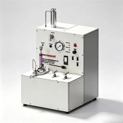
- Consistometer Thickening Time Profiling: Slurry samples are conditioned under simulated geothermal temperature and pressure ramp schedules. Thickening time to 70 Bc must equal planned placement duration plus an engineered 90 to 120-minute safety cushion.
- HPHT Stirred Fluid Loss Testing: Filtration volume is measured across a certified 325-mesh screen under 1,000 psi differential nitrogen pressure at bottom-hole circulating temperature (BHCT). High-pressure gas intervals require filtration loss below 35 mL/30 min.
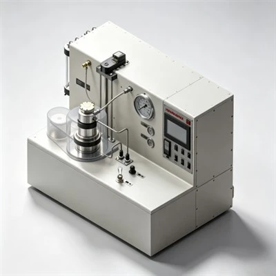
- Compressive Strength Analysis on UCA: Static strength development is monitored non-destructively using an Ultrasonic Cement Analyzer (UCA) under bottom-hole static temperature (BHST). The slurry must develop 500 psi strength within 12 to 16 hours.
- Free Fluid and Sedimentation Checks: Conditioned slurry poured into an undisturbed 250 mL glass cylinder must exhibit 0.0% free fluid breakout for gas-bearing and deviated intervals to prevent high-side water channeling.
Frequently Asked Questions (FAQ) Regarding Well Cementing Processes
1. Why are bottom and top wiper plugs essential in primary cementing?
The bottom plug wipes residual drilling mud from the casing inner wall and prevents mud-cement intermixing, while its rupture diaphragm permits cement passage upon reaching the float collar. The top plug follows the cement column, wiping cement from the casing wall and providing a definitive surface pressure indication ("plug bump") when landing on the float collar.
2. How does casing centralization influence cementing displacement efficiency?
In an un-centralized casing string resting against the borehole wall, cement slurry flows preferentially through the wide annular space where fluid resistance is lowest, leaving drilling mud trapped in the narrow side. Centralizers maintain casing standoff (>80%), ensuring uniform annular clearance and complete mud displacement around the pipe circumference.
3. What causes sustained casing pressure (SCP) after primary cementing?
Sustained casing pressure is typically caused by micro-annular gas channeling during the static gel strength transition (100 to 500 lbf/100 ft²), residual mud channels left along the casing wall, or cement sheath debonding due to thermal and pressure cycling during subsequent production.
Strategic Recommendations for Flawless Cementing Process Execution
In modern energy development, achieving multidecade well integrity depends directly on mastering what is the process of cementing. Integrating precision laboratory formulation, effective borehole conditioning, mechanical wiper plug sequences, and post-job acoustic logging eliminates downhole flash setting, prevents formation breakdown, and guarantees complete hydraulic containment.
KELIOIL remains committed to manufacturing high-performance oilfield cementing additives under strict ISO 9001 and API Spec 10A quality control standards. By combining state-of-the-art polymer synthesis with comprehensive laboratory testing support, KELIOIL empowers operating companies and service contractors worldwide to optimize chemical additive packages, eliminate downhole cementing failures, and ensure life-of-well asset integrity.
Optimize Your Cementing Processes with KELIOIL Additives
Our technical chemical specialists provide customized slurry formulation designs, API Spec 10A laboratory testing verification, and reliable bulk chemical supply of premium cementing additives tailored to demanding onshore and offshore drilling operations.