
Introduction
In primary and secondary oil well cementing operations, selecting the optimal fluid loss additive (FLA) is one of the most critical decisions affecting slurry performance, initial well integrity, and long-term zonal isolation quality. Far from being a simple chemical purchasing choice, the selection of a cementing fluid loss additive directly influences a matrix of interacting properties. These include slurry rheology, thickening time, free fluid control, compressive strength development, and gas migration control.
Choosing an incompatible or sub-optimal fluid loss agent often leads to catastrophic, high-cost field failures, such as:
- Excessive fluid loss into permeable formations, causing premature slurry dehydration (flash setting).
- Slurry instability and severe particle sedimentation in low-density systems, resulting in density gradients.
- Unpredictable thickening time, leading to either premature setting in the casing or delayed hydration that stalls rig time.
- Poor cement-to-casing bonding and the formation of a micro-annulus.
- Gas channeling during the cement transition phase, creating long-term structural leakage risks.
Conversely, a properly engineered fluid loss additive system ensures predictable performance under harsh downhole conditions and enhances well integrity. This comprehensive guide provides a structured engineering decision framework for selecting the right fluid loss additive for cement slurry design, blending practical field insights, laboratory testing logic, and modern oilfield chemistry.

1. The Multifunctional Role of Fluid Loss Additives in Cementing Systems
The fundamental purpose of a fluid loss additive in cementing is to control the filtration rate of the liquid phase (aqueous filtrate) into permeable rock matrices under differential pressure during placement and early static periods.
Engineering Mechanism: [High Differential Pressure] → Slurry Matrix with FLA → Polymeric Film Formation → [Controlled Filtrate Loss (<50 mL)]
Primary Technical Functions
- Filtration Control: Restricting water loss under high-pressure differentials to prevent localized dry-packing.
- Maintaining Water-Cement Ratio: Ensuring the slurry retains its engineered water content for complete chemical hydration.
- Supporting Hydration Kinetics: Protecting the matrix structure so that Class G cement or other binders hydrate uniformly.
- Eliminating Free Fluid: Reducing water separation at the upper sections of vertical or highly deviated wellbores.
The Shift to Multifunctional Performance
Modern oilfield chemistry has evolved. Today's premium fluid loss agents are no longer single-function polymers; they are multifunctional systems that actively regulate cement slurry rheology, enhance particle suspension stability, act as gas migration inhibitors, and assist high-temperature retarders in controlling thickening curves.
2. Key Engineering Parameters Driving the Selection Process
An additive should never be selected in isolation. Wellbore physics, thermodynamics, and geological constraints dictate the required polymer characteristics.
2.1 Temperature Regimes (BHCT & BHST)
Temperature is the ultimate limit for organic polymers. The Bottom Hole Circulation Temperature (BHCT) and Bottom Hole Static Temperature (BHST) classify the selection into three distinct zones:
- Low Temperature (<60°C / 140°F): Hydration is naturally slow. The selected fluid loss agent must possess low retarding side-effects to avoid delaying early compressive strength development ("waiting on cement" or WOC time).
- Medium Temperature (60°C to 120°C / 140°F to 248°F): Requires a balanced linear or modified copolymer that stabilizes filtration without drastically altering rheological properties.
- High-Temperature / HPHT (>120°C to 180°C+ / >248°F to 356°F): Standard polymers undergo thermal thinning and chain scission. HPHT cementing demands advanced, thermally stable synthetic copolymers (such as AMPS-based chemistry) that resist thermal degradation and salt contamination.
2.2 Slurry Density Boundaries and Particle Interaction
The design density of the slurry changes how particles interact inside the annulus. Crucially, different densities present entirely opposite risk factors:
| Slurry Classification | Density Range (g/cm³) | Dominant Risk Factor | Required Fluid Loss Additive Feature |
|---|---|---|---|
| Lightweight Systems | 1.20 – 1.60 | High sedimentation, particle settling, and free water separation due to high water-to-solid ratio. | Must provide exceptional anti-sedimentation and structural suspension properties to keep slurry homogeneous. |
| Standard Systems | 1.60 – 1.90 | Balanced filtration and rheology | Standard fluid loss control with predictable linear rheological properties. |
| Heavyweight Systems | >1.90 | Excessive plastic viscosity, over-flocculation, and high circulating friction pressures due to dense solid packing. | Must exhibit excellent particle dispersion properties to keep the system pumpable without excessive friction. |
2.3 Formation Permeability and Differential Pressure (ΔP)
High-permeability sandstones, depleted reservoirs, and highly fractured carbonates lose filtrate rapidly under high hydrostatic columns. If the differential pressure (ΔP) between the cement column and the formation pore pressure is wide, the fluid loss additive must form an exceptionally low-permeability polymer cake almost instantaneously on the borehole wall.
2.4 Thickening Time Safety Windows
The fluid loss additive must complement the high-temperature retarder. It should provide a flat, predictable consistency profile (measured in Bearden Units of Consistency, Bc) that terminates in a sharp "right-angle set" during API fluid loss testing and thickening trials, preventing erratic viscosity spikes during displacement.
3. Classifying Fluid Loss Additives: Types and Behavioral Profiles
Understanding the molecular and behavioral differences between additive families allows engineers to match the chemical to the specific well challenge.
3.1 Synthetic Polymer-Based Systems (AMPS Copolymers)
These high-molecular-weight synthetic polymers are the workhorses of modern deepwater and high-temperature wells.
- Advantages: Exceptional fluid loss control at temperatures up to 150°C–180°C; highly resistant to calcium, brine, and high-salinity mixing waters.
- Limitations:High manufacturing cost; can cause an increase in initial slurry viscosity if over-dosed.
3.2 Cellulose-Based Systems (HEC / CMHEC)
Modified natural polymers like Hydroxyethyl Cellulose (HEC) are widely used in shallow, low-temperature wells.
- Advantages: Highly cost-effective; excellent initial water-retention properties; broad compatibility with basic cement blends.
- Limitations: Highly sensitive to thermal degradation at temperatures exceeding 90°C (194°F); vulnerable to bacterial breakdown during storage.
3.3 Dispersible Anti-Sedimentation Systems (Advanced Dual-Function Systems)
Next-generation additives, such as the CG Series systems, represent a shift toward integrated slurry engineering.
- Advantages: These materials combine synthetic polymer filtration control with specific functional groups that improve particle dispersion. They prevent solids settling in lightweight cement slurries and provide exceptional gas migration resistance by tightening the slurry's micro-matrix during its critical transition state.
- Limitations: Requires precise laboratory tuning to optimize the balance between dispersion and setting kinetics.
4. A Structured 5-Step Engineering Decision Framework
To eliminate guesswork on the rig site, operators should implement this standardized engineering workflow when selecting fluid loss chemicals:
- Step 1: Define the Absolute Well Conditions
Document the hard environmental constraints: BHCT, BHST, maximum expected mud density, structural well geometry (vertical vs. extended-reach horizontal), and formation fracture gradients.
-
- Step 2: Establish Slurry Performance Targets
Determine the target operational parameters: Target slurry density (g/cm³), target API fluid loss limit (≤50 mL for production casings, ≤100 mL for surface casings), required pumping window safety margin, and target 24-hour compressive strength.
-
- Step 3: Identify the Dominant Risk Driver
Isolate the primary threat to a successful cement job. Is the temperature extremely high? Prioritize temperature stability. Is the slurry density ultra-low (e.g., 1.30 g/cm³)? Prioritize anti-sedimentation behavior. Is there a high-pressure gas zone? Prioritize gas migration control.
-
- Step 4: Select the Matching Additive Family
- Standard shallow well → Cellulose-based system.
- Deep, high-salinity, or moderate-temperature well → Synthetic copolymer system.
- Critical lightweight or HPHT gas well → Dispersible dual-function system (CG Series).
- Step 5: Perform Stringent Laboratory Validation
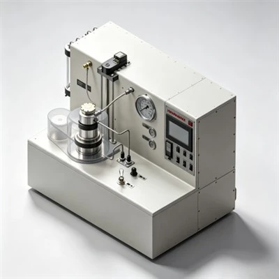
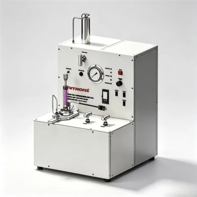
Validate the selected chemical using API RP 10B-2 standard testing protocols. Run the API Fluid Loss Test strictly at target temperature under 6.9 MPa (1000 psi) differential pressure. Also measure free water at a 45° incline, rheology profiles, and static gel strength transition times.
-
5. Critical Mistakes to Avoid in the Selection Process
- Mistake 1: Selecting Based Solely on Fluid Loss Volume (VAPI)
An additive that delivers a low fluid loss value of 25 mL in the lab can still cause field failures if it thins out drastically at static temperatures, causing solids settling and creating a weak density gradient along the upper casing.
-
- Mistake 2: Overlooking Sedimentation in Lightweight Slurries
When designing low-density slurries, engineers often focus on filtration while ignoring particle settling. Without an integrated anti-sedimentation additive or a dispersible fluid loss agent, the high-water slurry will separate downhole, undermining well integrity.
-
- Mistake 3: Testing Only at Room Temperature
A fluid loss polymer may show excellent performance at 25°C (77°F) but break down rapidly when exposed to a BHST of 130°C (266°F). Always perform validation testing at full simulated downhole temperature and pressure.
-
- Mistake 4: Ignoring Cross-Chemical System Compatibility
Some synthetic fluid loss polymers can interact poorly with specific lignosulfonate retarders or silicone-based defoamers. This chemical interference can lead to extreme slurry thickening or severe retardation.
-
6. Real-World Selection Matrices: Practical Engineering Examples
Scenario A: Offshore Deepwater Lightweight Casing (1.45 g/cm³ / 105°C BHST)
- The Challenge: High risk of free water separation, particle sedimentation, low fracture gradient, and weak formations.
- The Solution: A dispersible, anti-sedimentation fluid loss system (such as CG212S-P).
- Engineering Reason: Standard polymers cannot prevent water separation and solid settling at this low density; a dual-functional system ensures a uniform cement column with zero free fluid.
Scenario B: Ultra-Deep HPHT Production Liner (1.95 g/cm³ / 145°C BHST)
- The Challenge: Extreme thermal stress, heavy weighting agents (barite/hematite), high risk of polymer degradation, and high gas migration risks.
- The Solution: A high-molecular-weight AMPS synthetic copolymer paired with a silica flour stabilizer.
- Engineering Reason: High-density weighting agents create severe rheological stress. Highly stable synthetic polymers provide the thermal resistance needed to prevent fluid loss failure at 145°C while keeping the slurry fluid enough to pump easily without over-flocculating.
7. Future Trends: From Chemical Sourcing to Integrated Slurry Design
The oilfield cementing industry is moving away from brand-centric purchasing toward performance-based additive selection. Modern asset managers prioritize:
- Integrated Slurry Formulations: Moving away from single-product fixes in favor of multi-functional additives that simplify liquid blending and bulk mixing.
- Digital and Predictive Modeling: Using advanced slurry simulation software to predict fluid loss behavior and static gel strength development before mixing on-site.
- Customized Cost Optimization: Reducing dependence on expensive, sole-source global chemical brands by shifting toward cost-effective, high-performance alternative additive lines.
Conclusion
Selecting the right fluid loss additive for oil well cementing is a multi-parameter engineering process that directly impacts the lifespan of an oil or gas well. By moving away from basic, single-point evaluation and adopting a structured decision framework-one that balances temperature, density, cross-chemical compatibility, and anti-sedimentation properties-engineers can design robust slurry systems that lower operational risks, control chemical costs, and ensure long-term well integrity.