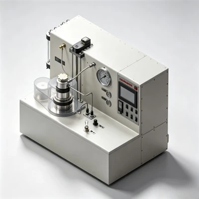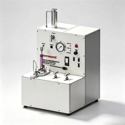

In oil well cementing operations, controlling the fluid loss of cement slurry is critical to maintaining slurry stability, preventing formation damage, and achieving reliable zonal isolation. Cement slurry is a concentrated suspensions of Portland cement, water, and performance chemical additives. When exposed to permeable downhole formations under hydrostatic pressure differential, water naturally filters into the formation matrix while solid cement particles accumulate on the borehole wall. This fluid filtration-known as fluid loss-can severely alter slurry rheology, induce premature flash gelation, trigger gas migration channels, and damage sensitive hydrocarbon reservoirs. Modern well completion strategies mitigate fluid filtration by deploying high-performance polymer fluid loss additives alongside laboratory evaluation using standardized HTHP fluid loss cells to verify filtrate control prior to field displacement.
Explore High-Performance Cementing Solutions:
Explore Salt-Resistant Fluid Loss Additive Solutions
Why Is Fluid Loss Control Critical in Well Cementing Operations?
Uncontrolled fluid loss during oil well cementing severely jeopardizes the structural and hydraulic integrity of the wellbore. As liquid filtrate leaks into permeable sandstones or carbonates, the solids-to-liquid ratio within the remaining cement column rapidly increases. This localized dehydration thickens the slurry, dramatically spiking plastic viscosity and yield point. The resulting frictional pressure spikes during surface pumping can exceed formation fracture thresholds, causing induced losses, lower top-of-cement (TOC) heights, and incomplete annular coverage across target zones.
Furthermore, rapid loss of mixing water accelerates cement hydration kinetics, drastically shortening pumpable thickening time. In deep high-temperature, high-pressure (HTHP) horizontal wells, uncontrolled fluid filtration creates static bridge plugs across high-permeability zones, preventing full displacement of the cement volume and sticking the casing string in place. Water filtration also damages sensitive producing formations by causing clay swelling and pore throat plugging, while simultaneously allowing formation fluids and natural gas to micro-channel behind the cement sheath.
Prior to slurry injection, engineers design comprehensive displacement trains featuring specialized pre-flushes and heavy spacer fluids to scour filter cake from the borehole wall. During pumping, operators incorporate chemical additives such as specialized salt-resistant fluid loss additives into the formulation to maintain consistent slurry density, preserve hydrostatic pressure control, and guarantee gas-tight annular sealing.
What Are the Primary Operational Risks Associated with High Slurry Dehydration?
When cement slurry suffers excessive fluid filtration downhole, multiple operational failure modes can occur in rapid succession, compromising the entire well construction investment:
- Premature Flash Gelation and Bridging: Rapid water removal increases the volume fraction of solid cement particles, transforming a free-flowing fluid into a high-viscosity paste. This paste forms localized annular bridges, blocking slurry flow and forcing pumping pressure up to emergency safety limits.
- Interrupted Slurry Placement: Severe fluid loss shortens the thickening time predicted by standard laboratory schedules. If the cement sets inside the casing or lower annulus before full displacement, costly drill-out or casing recovery operations become necessary.
- Formation Fracture and Lost Circulation: As frictional pressure increases due to dehydrated slurry, downhole equivalent circulating density (ECD) climbs rapidly. In fragile formations, this ECD spike exceeds the fracture gradient, breaking the rock matrix and causing total loss of cement returns.
- Micro-Annular Gas Channels: As water leaks into permeable formations, hydrostatic head pressure drops below pore pressure before the cement develops sufficient static gel strength. High-pressure gas invades the matrix, forming micro-annular gas channels that lead to sustained casing pressure (SCP).
What Are the Physical Mechanisms of Polymeric Fluid Loss Agents?
Chemical fluid loss control agents in well cementing operate primarily through two distinct physical mechanisms: filter cake deposition and aqueous phase viscosity modification.
Water-soluble synthetic polymers, particularly those formulated with 2-acrylamide-2-methylpropanesulfonic acid (AMPS), exhibit high thermal stability and resistance to divalent ions like calcium and magnesium. When dispersed in cement slurry, these high-molecular-weight chains hydrate and form a dense polymer network around hydrating cement particles.

Filter Cake Structure Building: As differential pressure forces water out of the slurry toward the rock formation, hydrated polymer molecules become trapped alongside fine cement particles at the borehole wall. This forms an ultra-thin, compressible, and low-permeability filter cake. The dense cake acts as a physical barrier that restricts further filtrate penetration into the formation matrix.
Viscosity Amplification and Pore Throat Blocking: In addition to cake formation, dissolved polymer chains increase the viscosity of the pore fluid within the slurry matrix. According to Darcy's law, fluid filtration velocity is inversely proportional to liquid phase viscosity. By raising filtrate viscosity and physically plugging pore throat micro-channels, synthetic fluid loss polymers hold mixing water within the slurry even under harsh downhole differential pressures.
To explore operational details regarding fluid displacement dynamics and rheological control during displacement, review our comprehensive guide on engineering steps in primary well cementing execution.
Key Types of Cementing Fluid Loss Additives and Their Capabilities
Selecting the appropriate fluid loss agent depends on bottom-hole temperature, water salinity, shear stress, and slurry density demands:
| Additive Class | Chemical Backbone | Temperature & Salinity Limits | Primary Operational Benefit |
|---|---|---|---|
| AMPS Synthetic Copolymers | AMPS / Acrylamide Graft Polymers | Up to 400°F (204°C); High-salinity / Saturated Brine | Exceptional thermal stability and salt resistance with minimal impact on setting time. |
| Cellulosic Polymers (HEC / CMHEC) | Modified Hydroxyethyl Cellulose | Low to Medium Temp (< 230°F / 110°C); Fresh Water | Cost-effective filtration control in shallow surface casing strings. |
| PVA & Synthetic Gums | Polyvinyl Alcohol Blends | Moderate Temp (< 260°F / 127°C); Mild Salinity | Low viscosity contribution, enabling high-density slurry placement. |
| Particulate Latex Systems | Styrene-Butadiene Rubber Emulsions | Up to 350°F (177°C); Versatile Water Chemistry | Superior gas-channeling prevention and enhanced set cement elasticity. |
How Laboratory Testing Standardizes Slurry Filtration Control
Standardized laboratory qualification under API RP 10B-2 guidelines ensures that cement slurry formulations deliver target fluid loss control before mixing and pumping at the wellsite.

Static HTHP Fluid Loss Cell Testing: Standard static fluid loss cells apply 1,000 psi (6.9 MPa) differential pressure using compressed nitrogen gas across a 325-mesh screen at simulated bottom-hole static temperature (BHST). The liquid filtrate collected in a graduated cylinder over 30 minutes represents the API fluid loss value. Critical production strings and gas-bearing reservoirs typically require API fluid loss values under 30 to 50 mL/30 min.
Stirred HTHP Fluid Loss Testing: Stirred fluid loss cells incorporate internal paddles that agitate the slurry during heating and pressurization, replicating continuous dynamic shear during placement. This qualification method evaluates filter cake integrity under mechanical shear, confirming fluid loss performance under realistic wellbore conditions.
Understanding how thermal degradation affects high-temperature chemical retarders and fluid loss polymer chains is vital for deep well design; explore our technical analysis on chemical mechanisms of high-temperature cementing retarders to see how setting dynamics are managed under harsh downhole environments.
Case Application: Delaware Basin High-Temperature Liner Cementing
In the Delaware Sub-basin of the Permian Basin (Texas, USA), operators drilling extended-reach horizontal wells into the Wolfcamp formation face narrow margin pressure windows, high bottom-hole temperatures up to 320°F (160°C), and severe gas migration threats.
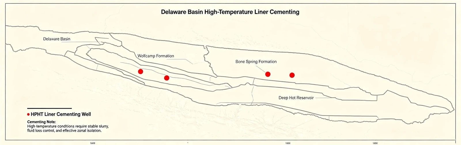
Regional Background & Technical Challenges: Lateral production liners extended past 20,000 feet total depth through permeable depleted sands. Previous conventional slurries suffered high fluid loss exceeding 180 mL/30 min, causing premature dehydrated bridging inside the narrow casing annulus, stuck pipe incidents, and persistent sustained casing pressure (SCP) caused by gas channeling.
Chemical Solution & Testing Protocol: The engineering team developed a customized 16.0 ppg slurry incorporating synthetic AMPS-based fluid loss additives, polymer retarders, and dispersants. Pre-job HTHP fluid loss cell tests confirmed API filtrate loss below 28 mL/30 min at 320°F with low plastic viscosity, maintaining pumpability across 7-hour placement windows.
Application Results: Displacement achieved 100% full slurry returns across the horizontal lateral without pressure spikes or dynamic loss. Acoustic cement bond logs (CBL/VDL) demonstrated complete annular fill and hydraulic sealing across all target production zones.
Best Practices for Optimizing Field Slurry Formulations
Field engineers follow proven practices to ensure fluid loss additives deliver consistent, reproducible results during cementing operations:
- Verify Water Compatibility: Pre-test mix water for total dissolved solids (TDS), calcium ions, and pH. High hardness can inhibit polymer hydration if not compensated with salt-tolerant additives.
- Balance Dispersant Dosage: Maintain proper dispersant ratios to ensure smooth polymer hydration while preventing slurry particle settling or free water separation.
- Account for Shear History: High mixing shear in field batch mixers can temporarily alter polymer viscosity; ensure laboratory pre-job testing mirrors field shear rates.
- Conduct Pre-Job Quality Assurance: Perform point-of-use liquid filtrate measurements with portable fluid loss cells at the wellsite prior to pumping downhole.
Securing Long-Term Well Integrity with Chemical Innovation
Maintaining tight control over cement slurry fluid loss is foundational to achieving long-term hydraulic zonal isolation, protecting producing formations, and preventing annular fluid migration. By combining high-efficiency synthetic fluid loss additives, high-temperature retarders, and precise laboratory testing using HTHP fluid loss cells and viscometers, drilling operators can eliminate costly remedial cementing interventions and ensure structural integrity throughout the operational lifespan of the wellbore.
For broader technical background on comprehensive chemical formulation strategies across diverse wellbore architectures, review our overview on essential oil well cementing additives and chemical formulations.
Optimize Your Oil Well Cementing Formulations Today
We supply high-grade cementing additives, retarders, and fluid loss control agents compliant with API Spec 10A standards, alongside laboratory cement testing equipment for global field operations.
Request Technical Pricing for Cementing Solutions