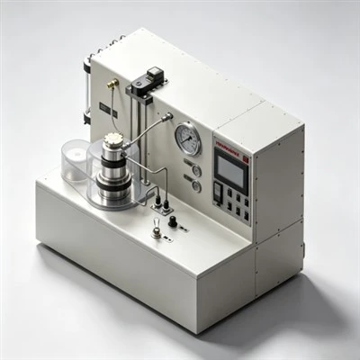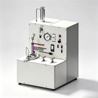

Well cementing secures oil and gas wells by pumping an engineered cement slurry into the casing-formation annulus to establish permanent hydraulic isolation, structural support, and corrosion protection. In primary well cementing, the cement slurry seals open-hole formations immediately after drilling to prevent zonal fluid migration and support heavy casing strings. In remedial well cementing, specialized slurries seal casing leaks, repair micro-annular channels, and support permanent plug and abandonment (P&A) programs. Modern well cementing performance relies on high-grade chemical additives-including fluid loss additives, retarders, dispersants, and defoamers-alongside precise laboratory testing using HTHP consistometers and rotational viscometers to verify slurry rheology, thickening time, and compressive strength before field pumping.
Explore High-Performance Cementing Solutions:
Explore Cementing Additives Portfolio
How Does Well Cementing Establish Long-Term Zonal Isolation?
Well cementing creates a continuous, impermeable seal between the outer steel casing wall and the drilled geological formation. Without effective well cementing, high-pressure subsurface fluids such as natural gas, crude oil, and saline formation water can migrate freely behind the casing sheath. This unwanted interzonal cross-flow risks contaminating shallow fresh-water aquifers, corroding structural tubulars, and causing catastrophic surface blowouts. Successful well cementing depends on displacing drilling mud completely, maintaining exact slurry rheology, and ensuring the hydrated cement sheath achieves high compressive strength and low permeability under dynamic downhole stress.
The operational process of well cementing begins immediately after reaching target drilling depth. Drilling crews pull the drill string out of the hole (POOH) and run the heavy steel casing string to the bottom seat. Centralizers mounted along the casing string keep the pipe centered within the borehole, preventing the casing from resting against the low side of horizontal or directional wellbores. Proper centralization is vital for well cementing because an off-center casing leaves narrow annular gaps where drilling mud becomes trapped, creating continuous mud channels through which gas and water can later leak.
Prior to injecting the cement slurry, drilling mud pre-flushes and high-viscosity spacer fluids are pumped into the annulus. Because drilling fluids and Portland cement slurries are chemically incompatible, direct mixing causes rapid gelation, sharp pressure spikes, and incomplete mud removal. Chemical spacers scour filter cake from the formation face and physically separate drilling mud from the approaching cement column. During this displacement phase, operators incorporate specialized fluid loss additives into the slurry formulation to limit water filtration into permeable rocks, maintaining stable slurry density and preventing flash hydration during well cementing operations.
What Are the Operational Stages of Primary Well Cementing?
Primary well cementing is executed in a continuous, highly controlled pumping sequence designed to isolate formation zones and support the structural integrity of the wellbore. The physical pumping operation relies on a multi-stage wiper plug system that separates chemical fluids inside the casing string:
- Pre-Flush and Spacer Pumping: Chemical washes and weighted spacer fluids clear filter cake, condition the borehole wall, and prevent contamination between drilling mud and the main cement column during well cementing.
- Bottom Wiper Plug Launching: A elastomeric bottom wiper plug is released ahead of the cement slurry volume. As it travels down the inner casing, it wipes residual drilling mud off the internal pipe walls to prevent slurry contamination.
- Cement Slurry Injection: The pre-mixed cement slurry containing high-temperature retarders, dispersants, and fluid loss additives is pumped into the casing under controlled flow rates to achieve laminar or turbulent annular displacement during well cementing.
- Rupturing the Diaphragm: When the bottom plug lands on the float collar or casing shoe, increased surface pump pressure ruptures a rubber diaphragm inside the plug, allowing the cement slurry to flow out into the casing-formation annulus.
- Top Wiper Plug Launching and Displacement: A solid top plug is launched behind the final volume of cement, followed by displacement fluid (mud or brine). The top plug physically separates displacement fluid from the cement slurry during well cementing.
- Plug Bumping and Shut-In: Once the top plug seats firmly against the bottom plug, a sharp pressure spike ("bump") confirms complete placement. Pumping stops, back-pressure valves close, and the cement column is left undisturbed to hydrate during well cementing.
For operational comparisons regarding fluid displacement dynamics and rheological control during pumping, see our detailed guide on engineering steps in primary well cementing execution.
Essential Chemical Additives Used in Oil Well Cementing
Neat Portland cement alone cannot withstand the complex thermal and pressure regimes encountered in modern oilfield environments. Over a hundred chemical additives have been developed to engineer slurry rheology, setting kinetics, mechanical endurance, and fluid loss control during well cementing:
| Additive Category | Primary Mechanism | Key Operational Benefit in Well Cementing |
|---|---|---|
| Fluid Loss Control Agents | Form synthetic polymer film across permeable formation pores | Prevents premature dehydration, maintains slurry volume, and blocks gas channeling during well cementing. |
| Cementing Retarders | Delay tricalcium silicate (C3S) hydration phase under elevated temperatures | Extends thickening time for long-distance placement in deep HPHT well cementing applications. |
| Cement Dispersants | Neutralize particle charges to disperse cement grain clusters | Reduces slurry viscosity, lowers surface friction pressure, and promotes turbulent annular flow. |
| Accelerators | Speed up hydration kinetics in low-temperature environments | Shortens Wait-on-Cement (WOC) time and accelerates early compressive strength development. |
| Defoamers & Anti-Foamers | Break surface tension of trapped air bubbles during surface mixing | Prevents slurry density fluctuations and pump cavitation during well cementing operations. |
High-temperature applications require advanced synthetic chemistry. Incorporating specialized polymer additives prevents premature slurry setting during deep horizontal displacement, enabling predictable thickening times up to 350°F (177°C).
Understanding how thermal acceleration and downhole pressure affect hydraulic seals is vital for field engineers; review our analysis on chemical mechanisms of high-temperature cementing retarders to see how setting dynamics are controlled under harsh reservoir conditions.
How Do Laboratory Testing Instruments Verify Slurry Performance?
To guarantee well cementing success, slurry formulations undergo rigorous testing in specialized oilfield laboratories according to API Spec 10A standards prior to field deployment:
Thickening Time Testing: An HTHP consistometer simulates bottom-hole circulating temperature (BHCT) and bottom-hole static pressure (BHST). The consistometer measures slurry consistency in Bearden Units of Consistency (Bc). A flat thickening curve-maintaining low consistency under 30 Bc followed by a rapid transition to 100 Bc-confirms the cement slurry will remain pumpable during well cementing without setting prematurely in the casing.
Dynamic Rheology Measurement: A coaxial rotational viscometer evaluates slurry flow profiles across multiple rotational speeds. Laboratory technicians measure plastic viscosity (PV) and yield point (YP) to confirm optimal hydraulic displacement and verify that surface pumping pressure will remain within safety limits during well cementing.
Fluid Loss and Compressive Strength Testing: Standard HTHP fluid loss cells subject the slurry to 1,000 psi differential pressure across a 325-mesh screen to quantify filtrate volume loss (target < 50 mL/30 min for gas tight slurries). Concurrently, Ultrasonic Cement Analyzers (UCA) measure non-destructive acoustic velocity to continuously track early compressive strength development during well cementing hydration.
Casing Architecture and Annular Seal Requirements
A typical wellbore architecture features concentric steel casing strings engineered to withstand formation pressures and tectonic forces. Each casing string demands targeted slurry designs during well cementing:
- Conductor Casing (20" to 30"): Prevents washout of loose, unconsolidated surface soil and routes returning drilling fluids during well cementing. Accelerated, low-density slurries are commonly used.
- Surface Casing (13-3/8" to 16"): Protects fresh-water aquifers, anchors surface blowout preventers (BOP), and supports structural well loads. Rapid compressive strength development is required during well cementing.
- Intermediate Casing (8-5/8" to 10-3/4"): Isolates abnormal pressure zones, sloughing shale formations, and loss-circulation zones. Highly dispersed, retarder-treated slurries ensure complete coverage during well cementing.
- Production Casing / Liner (4-1/2" to 7"): Seals the target hydrocarbon reservoir, resists production fluid corrosion, and sustains hydraulic fracturing pressures. Gas-tight, expandable slurries are critical for well cementing integrity.
For deeper insights into how specialized chemical systems optimize complex slurry systems across varied casing programs, explore our technical breakdown on essential oil well cementing additives and chemical formulations.
Remedial Well Cementing Techniques: Squeeze and Plug Placement
When primary well cementing yields incomplete annular coverage, micro-annular channels, or casing leaks, remedial cementing interventions are performed to restore wellbore integrity:
Squeeze Cementing: High-pressure surface pumps force a high-solids, low-fluid-loss cement slurry through targeted casing perforations into formation voids, micro-annuli, or behind damaged pipe. Squeeze well cementing establishes hydraulic isolation across leaking zones, seals depleted formations, and repairs failed casing shoe integrity.
Plug and Abandonment (P&A): At the end of a well's productive life, heavy cement plugs are placed across open intervals and casing shoes to permanently isolate oil, gas, and water zones. Quality P&A well cementing prevents surface environmental contamination and long-term hydrocarbon leakage.
Case Application: Permian Basin HPHT Production Liner Operations
In the Permian Basin (Delaware Sub-basin, USA), operators drilling long horizontal laterals in the Wolfcamp and Bone Spring formations face high bottom-hole temperatures exceeding 310°F (154°C) and severe fluid loss conditions during well cementing.

Regional Background & Technical Challenges: Lateral production liners extending past 18,000 feet deep encounter narrow pressure windows between formation pore pressure and fracture gradients. Standard cement formulations previously suffered from high filtrate loss and flash gelation, leading to stuck casing and interzonal gas migration during well cementing.
Chemical Solution & Execution: The engineering team deployed an engineered 15.8 ppg slurry formulation incorporating synthetic polymer fluid loss additives, high-temperature retarders, and specialized dispersants. Pre-job HTHP consistometer testing verified a flat 6-hour thickening profile at 315°F with API fluid loss controlled below 32 mL/30 min.
Application Results: Efficient pre-flush spacer displacement scoured oil-based mud cakes, enabling smooth slurry placement across the entire horizontal section. Post-job radial acoustic bond logging confirmed 98% zonal isolation efficiency through the producing interval, achieving gas-tight well cementing integrity and eliminating micro-annular leaks.
Achieving Sustainable Well Integrity through Chemistry and Testing Synergy
Ensuring reliable zonal isolation throughout the lifecycle of an oil or gas well requires precise integration between chemical additive design, mechanical displacement execution, and laboratory qualification. By pairing high-grade fluid loss agents, temperature-stable retarders, and effective dispersants with standardized testing protocols on HTHP consistometers and rotational viscometers, drilling engineers can eliminate remedial repair costs, ensure compliance with environmental standards, and optimize well cementing efficiency across demanding global reservoirs.
Optimize Your Oil Well Cementing Formulations Today
We supply high-grade cementing additives, retarders, and fluid loss control agents compliant with API Spec 10A standards, alongside laboratory cement testing equipment for global field operations.
Request Technical Pricing for Cementing Solutions