
Evaluating how does a fluid loss additive protect the cement slurry requires examining the physical, chemical, and hydraulic defense mechanisms that prevent aqueous filtrate escape into permeable rock under extreme downhole differential pressures across deep onshore and offshore plays in the Middle East, North America, and deepwater basins. Analyzing how does a fluid loss additive protect the cement slurry demonstrates that by depositing a thin, micro-impermeable polymer-mineral filter cake and viscosifying pore water, these additives preserve the designed water-to-cement ratio, maintain consistent rheology, and suppress premature gelation. Implementing slurry systems engineered around how does a fluid loss additive protect the cement slurry stabilizes hydrostatic backpressure, eliminates micro-annular debonding, prevents severe gas channeling during the critical transition phase, and safeguards high-cost wells from catastrophic remedial squeeze operations.

The Operational Significance of Slurry Dehydration Prevention
In petroleum well construction, primary cementing serves as the definitive structural and hydraulic seal. It anchors the casing string within the drilled hole, isolates permeable hydrocarbon intervals, protects shallow freshwater aquifers from drilling contamination, and shields steel pipe from corrosive subterranean fluids such as hydrogen sulfide (H₂S) and carbon dioxide (CO₂). However, throughout dynamic displacement down casing tubulars and upward into the narrow subterranean annulus, the cement slurry column exerts hydrostatic pressure that substantially exceeds formation pore pressure.
Across permeable sandstones, carbonates, and micro-fractured shales, this differential overbalance drives aqueous mix water out of the slurry and into the subterranean rock. If water retention is unmanaged, the consequences are immediate and severe. As mix water escapes, the solid particle volume fraction spikes, triggering rapid slurry flash thickening. This localized dehydration increases plastic viscosity, elevating the equivalent circulating density (ECD) beyond formation fracture breakdown limits. The resulting hydraulic fracturing causes massive lost circulation, drops the top of cement (TOC) far below designed depths, and frequently wedges casing off-bottom, leaving drilling assemblies stuck in hole.
Investigating how does a fluid loss additive protect the cement slurry demonstrates how chemical filtration control establishes a protective barrier that preserves fluid design integrity. By maintaining the intended water-to-cement ratio under API Spec 10A and API RP 10B-2 testing protocols, fluid loss additives keep the cement slurry in a pumpable, homogenous state from the casing shoe to total measured depth. This water retention guarantees predictable pumping pressures, promotes uniform crystal growth during hydration, and ensures that the set sheath forms an impermeable mechanical barrier against formation gas invasion.
1. How Fluid Loss Additives Maintain Slurry Water Balance
Preserving designed water content is vital for maintaining slurry predictability. When water escapes into porous rock faces, the cement solids concentrate into an un-pumpable state. Fluid loss additives incorporate water-soluble synthetic polymers-such as 2-acrylamido-2-methylpropane sulfonic acid (AMPS) copolymers-and high-purity cellulose derivatives. These polymers unravel in the alkaline pore water, electrostatically binding free water molecules and depositing an ultra-thin, low-permeability polymer-mineral filter cake across the formation face.
By controlling filtration loss below 50 mL/30 min under API standard conditions, the additive stabilizes rheological properties, eliminates unexpected consistency spikes, and guarantees smooth, uninterrupted placement through narrow annular clearances.
Water Retention Performance Comparison
2. Prevention of Premature Thickening, Bridging, and Early Gelation
Premature thickening occurs when fluid loss increases the solid clinker concentration beyond critical packing limits. When solid grains contact one another directly without lubricating water films, inter-particle friction surges, triggering early mechanical gelation. This early structuring causes solids bridging across casing collars, centralizers, and borehole washouts, restricting annular flow paths.
A high-performance fluid loss additive suppresses this premature bridging. By maintaining a continuous aqueous phase, the polymer chains provide steric and electrostatic lubrication between hydrating particles. This extends the workable pumping window, allowing the cement to travel safely to target depth without unexpected viscosity jumps.
Premature Gelation Risk Comparison
3. Improving Set Cement Sheath Mechanical Properties and Bond Strength
A stable, non-dehydrating slurry directly produces a denser, mechanically superior set cement sheath. Fluid loss additives ensure that the designed water-to-cement ratio is preserved throughout hydration, preventing solids settling and free water channels. Free water breakout creates continuous water pockets along the high side of deviated wellbores, forming permanent micro-channels that ruin acoustic bond logs (CBL-VDL).
By promoting uniform hydration crystal growth, fluid loss additives minimize matrix permeability and eliminate interfacial micro-annuli between casing steel, cement, and formation rock, ensuring high compressive strength and permanent zonal isolation.
Cement Sheath Quality Comparison
4. Minimizing Reservoir Formation Damage and Skin Impairment
When cement filtrate escapes into producing hydrocarbon intervals, it carries alkaline calcium hydroxide (pH 12 to 13) and dissolved ions into delicate reservoir pore spaces. This alkaline invasion triggers severe subterranean damage: it destabilizes in-situ clay minerals, causing montmorillonite swelling, disperses mobile formation fines, and precipitates insoluble calcium carbonate (CaCO₃) scales in throat apertures. The resulting permeability loss reduces well productivity, requiring expensive remedial matrix acidizing treatments.
A high-efficiency fluid loss additive forms a low-permeability polymer cake on the rock surface, restricting filtrate depth of invasion to a few millimeters. This preserves reservoir permeability, protects fragile formation integrity, and eliminates fluid invasion that could trigger borehole collapse.
Formation Damage Comparison
5. Increasing Slurry Stability Under Extreme HPHT Conditions
High-pressure high-temperature (HPHT) environments accelerate water loss and can cause thermal degradation of low-tier additives. When bottom-hole static temperatures surpass 150°C to 200°C, traditional cellulosic polymers suffer ether linkage hydrolysis, breaking down into inactive fragments. HPHT-resistant fluid loss additives-primarily synthetic AMPS copolymers compounded with N-vinyl pyrrolidone (NVP)-maintain thermal chain stability up to 230°C (446°F), keeping filtration tightly controlled throughout prolonged static periods prior to initial set.
HPHT Additive Performance Comparison
6. Enhancing Additive Compatibility and Brine Tolerance
Modern cementing formulations contain multiple additives working together, including high-temperature retarders, dispersants, accelerators, lightweight microspheres, and anti-gas migration latexes. A high-performance fluid loss additive must integrate seamlessly with these chemistries without causing antagonistic flocculation, excessive viscosity, or delayed setting.
Furthermore, offshore and deep evaporite wellbores require slurries mixed with seawater, potassium chloride (KCl), or saturated sodium chloride (NaCl) brines. Conventional polyacrylamides precipitate in high ionic strength solutions. Synthetic AMPS-based additives maintain full water solubility and colloidal stability across diverse water systems.
Additive Compatibility Matrix
Regional Application Case: Deep Carbonate Sour Gas Production Liner Cementing in the Ahwaz Field, Khuzestan Province, Iran
Case Application: Ahwaz Oilfield, Khuzestan Province, Southwestern Iran

Target Formation: Deep HPHT Khami Sour Gas Carbonates (High Pressure, High H₂S & Narrow ECD Window)
Regional Cementing Background in Khuzestan Carbonate Plays
In the Ahwaz field of southwestern Iran, drilling operations penetrate overpressured gas-bearing carbonate reservoirs within the Cretaceous-Jurassic Khami Group. Well measured depths regularly exceed 4,900 to 5,300 meters (16,000 to 17,400 feet). Downhole conditions are severe: bottom-hole static temperatures (BHST) climb to 165°C to 175°C (329°F to 347°F) with formation pressures exceeding 12,000 psi (82.7 MPa). The formations produce sour gas containing H₂S (up to 6%) and CO₂ (up to 8%). Cementing 7-inch production liners across the Khami interval requires heavy Class G slurry systems (1.98 to 2.10 g/cm³) weighted with barite and stabilized by high-temperature polymers.
Regional Cementing Challenges in Extreme HPHT Formations
Operators cementing deep production liners across the Khami formation encounter critical technical hurdles:
- Severe Retarder Sensitivity: At temperatures above 160°C, minor variations of 0.05% BWOC in chemical retarder concentration cause large swings in thickening time, risking premature flash setting or multi-day setting delays.
- Narrow Equivalent Circulating Density (ECD) Windows: Close margins between formation pore pressure and fracture breakdown pressure demand low-viscosity slurries that maintain steady rheology without premature gelation spikes.
- Risk of Sour Gas Channeling: An extended transition time during slurry phase changes allows sour gas invasion into the decaying hydrostatic column, creating sustained casing pressure (SCP).
Technical Requirements for Slurry Qualification
To qualify a heavy 1.98 g/cm³ (16.5 ppg) Class G cement system across the Khami gas zone, the operator established strict performance criteria:
- API fluid loss control strictly below 35 mL/30 min at 165°C using an automated high-temperature stirred fluid loss cell to prevent dehydration.
- Thickening time validation on an HPHT consistometer confirming a pumpability window of 5 hours and 30 minutes to 70 Bc under simulated dynamic ramp schedules.
- Static gel strength (SGS) transition window (from 100 to 500 lbf/100 ft²) of less than 30 minutes, with 24-hour compressive strength exceeding 3,500 psi (24.1 MPa).
How Advanced Fluid Loss Technology Resolved the Field Challenge
Addressing these operational constraints required applying an exact engineering understanding of how does a fluid loss additive protect the cement slurry. The technical team formulated a Class G cement system utilizing KELIOIL synthetic AMPS salt-resistant fluid loss additives (1.8% BWOC) paired with high-temperature synthetic retarders, sulfonated dispersants, and 35% BWOC silica flour. The AMPS terpolymer formed an impermeable filter cake across the porous carbonate faces, maintaining API filtration loss at 32 mL/30 min under 165°C and 1,000 psi differential pressure.
Consistometer test curves confirmed a stable thickening time of 5 hours and 38 minutes to 70 Bc with zero early viscosity peaking. During field execution at Well Ahwaz-412, the slurry was pumped across the 1,050-meter liner without surface pressure surges or ECD spikes. Post-job radial acoustic cement bond logs (CBL-VDL) confirmed 100% circumferential bonding across the Khami sour gas pay zone. Subsequent negative pressure testing recorded zero sustained annular pressure, proving that precision chemical control based on how does a fluid loss additive protect the cement slurry provides the empirical foundation required to eliminate cementing failures in extreme HPHT plays.
Laboratory Testing Standards and Quality Assurance Protocols
Validating fluid loss additive performance requires standardized laboratory protocols adhering to API RP 10B-2 guidelines:
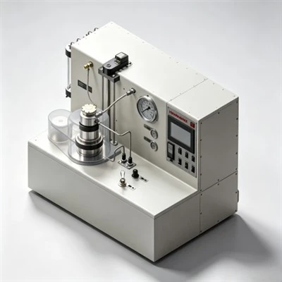
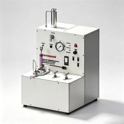
- High-Pressure High-Temperature (HPHT) Filter Press Testing: Slurry samples are conditioned in an atmospheric consistometer to bottom-hole circulating temperature (up to 88°C) or in an HPHT consistometer for higher temperatures, then transferred into an API stirred fluid loss cell. Differential nitrogen pressure of 1,000 psi (6.89 MPa) is applied across a certified 325-mesh (45-micron) stainless steel screen, and filtrate volume is collected at 30 seconds, 1 minute, 2 minutes, 5 minutes, 15 minutes, and 30 minutes.
- Testing with Actual Field Mix Water Batches: Dissolved salts, divalent calcium (Ca²⁺) and magnesium (Mg²⁺) ions, and pH variations in rig mix water alter polymer chain extension. Always test fluid loss additives using actual rig water samples rather than laboratory deionized water.
- Rheology and Compatibility Profiling: Measure plastic viscosity and yield point on rotational viscometers across 600, 300, 200, 100, 6, and 3 rpm. Verify that the fluid loss additive does not induce excessive slurry gelation or cause antagonistic flocculation when combined with dispersants.
- Free Fluid and Settling Checks: Conditioned slurry must be poured into a 250 mL glass cylinder and allowed to stand undisturbed at circulating temperature for 2 hours. Free fluid breakout must remain strictly below 1.0% (and 0.0% for gas-bearing intervals).
Frequently Asked Questions (FAQ) Regarding Slurry Protection via Fluid Loss Control
1. Why is fluid loss control critical during slurry transition from liquid to solid?
During the phase transition, static gel strength develops from 100 to 500 lbf/100 ft², and the cement column begins to support its own weight, causing hydrostatic pressure transmission to decay. If the slurry continues to lose water into the formation, pore pressure drops below formation gas pressure, allowing gas to channel upward through the setting cement. Maintaining fluid loss below 35 to 50 mL/30 min keeps pore water backpressure intact, preventing gas invasion.
2. How does fluid loss control prevent formation fracturing downhole?
Uncontrolled water loss causes solid cement particles to concentrate rapidly along permeable formation walls, forming thick, immovable filter cakes. This narrowing of the annular clearance causes frictional pumping pressures to surge. By preserving slurry fluidity, fluid loss additives keep equivalent circulating densities (ECD) within safe hydraulic limits, avoiding formation breakdown.
3. Can high dosages of fluid loss additives extend waiting-on-cement (WOC) time?
Yes. Overdosing fluid loss polymers can excessively coat cement grains, delaying early hydration kinetics and extending thickening times. Specialized AMPS-copolymer and PVA systems are engineered to provide tight filtration control without causing secondary retardation, allowing slurries to reach 500 psi compressive strength quickly.
Strategic Recommendations for Slurry Placement and Wellbore Integrity
In modern well construction, achieving permanent zonal isolation depends directly on empirical laboratory precision and chemical formulation science. Understanding how does a fluid loss additive protect the cement slurry enables drilling and completion teams to prevent slurry dehydration, maintain hydrostatic pressure transmission, and eliminate gas channeling.
KELIOIL remains committed to manufacturing high-performance oilfield cementing additives under strict ISO 9001 and API Spec 10A quality control standards. By combining state-of-the-art polymer synthesis with comprehensive laboratory testing support, KELIOIL provides operators and cementing service contractors worldwide with dependable fluid loss additives that guarantee wellbore integrity, protect the environment, and ensure long-term hydrocarbon asset productivity.
Protect Your Slurry Integrity with KELIOIL Fluid Loss Additives
Our technical chemical specialists provide customized slurry formulation designs, API Spec 10A laboratory testing verification, and reliable bulk supply of premium cementing additives tailored to demanding onshore and offshore drilling operations.