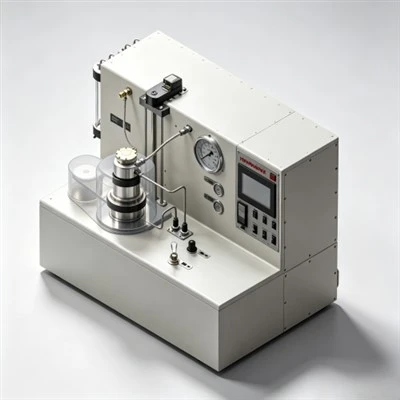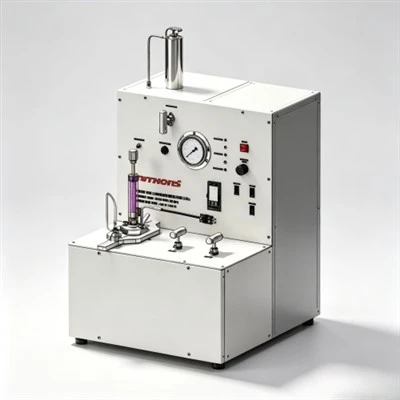

When petroleum engineers evaluate how does a fluid loss additive work in oilwell cementing, they investigate the chemical mechanisms that restrict aqueous filtrate escape into permeable subterranean formations under differential hydrostatic pressures across demanding deepwater and high-pressure high-temperature (HPHT) plays in the Middle East, the Gulf of Mexico, and the Tarim Basin. Exploring how does a fluid loss additive work in oilwell cementing reveals that synthetic AMPS-based polymers, modified cellulose derivatives, and latex emulsions deposit a dense, micro-impermeable polymer-mineral filter cake across the borehole face while increasing aqueous phase viscosity. Applying formulations designed around how does a fluid loss additive work in oilwell cementing maintains slurry design water-to-cement ratios, prevents premature slurry desiccation, suppresses equivalent circulating density (ECD) surges, and blocks gas micro-channeling during phase transitions.

The Operational Significance of Filtration Control in Wellbore Zonal Isolation
In hydrocarbon well construction, primary cementing represents the structural and hydraulic barrier required to anchor casing strings, isolate porous gas and oil zones, protect shallow freshwater aquifers, and shield casing steel from corrosive formation brines. Once mixed at surface, cement slurry is displaced down the casing string and up into the annular space between the pipe and the drilled geological formation. Throughout this placement process, the slurry column exerts hydrostatic pressure that exceeds the natural pore pressure of porous sandstone or carbonate formations.
Under this differential pressure gradient, water naturally tends to filter out of the slurry and invade the surrounding rock matrix. If filtration is left uncontrolled, the rapid loss of mix water alters the water-to-cement ratio, concentrates solid clinker particles, and triggers premature slurry dehydration. As a consequence, apparent slurry viscosity spikes rapidly, driving equivalent circulating density (ECD) beyond formation fracture breakdown limits. This causes severe lost circulation, leaves intervals un-cemented, and risks premature slurry setting inside casing strings, resulting in stuck pipe and multimillion-dollar sidetrack drilling operations.
Furthermore, uncontrolled water loss induces liquid phase volume shrinkage. As free mix water is absorbed into the formation, the effective hydrostatic head of the cement column decays rapidly during early hydration. If hydrostatic backpressure falls below formation gas pore pressure while the cement matrix remains permeable, gas invades the setting slurry, carving continuous channels to surface that create sustained casing pressure (SCP). Understanding how does a fluid loss additive work in oilwell cementing provides engineers with the chemical foundation to maintain filtration below 50 mL/30 min under API Spec 10A standards, ensuring steady rheology, predictable placement schedules, and long-term wellbore integrity.
Physicochemical Mechanisms: How Polymers Inhibit Filtrate Loss
To analyze how does a fluid loss additive work in oilwell cementing at the molecular level, chemists examine the interaction between polymeric macromolecules, hydrating cement mineral grains, and porous formation faces. Chemical filtration controllers operate through three coordinated physical and chemical mechanisms:
1. Polymer Adsorption and Impermeable Filter Cake Compaction
As cement slurry contacts a porous formation face under differential pressure, water begins to enter pore throats, dragging fine cement clinker particles with it. High-molecular-weight fluid loss polymers-such as AMPS copolymers or modified celluloses-adsorb onto hydrating calcium silicate and aluminate surfaces via hydrogen bonding and electrostatic attraction. The long polymer chains bridge between adjacent cement particles, forming an interconnected polymer-mineral mesh. As differential pressure compacts this layer against the rock face, the flexible polymer chains deform and compress into interstitial voids, creating a micro-impermeable filter cake with permeability lower than 10⁻⁴ millidarcies that stops water loss.
2. Aqueous Phase Viscosification and Water Structuring
Water-soluble polymers contain hydrophilic functional groups, such as sulfonic acid (–SO₃⁻), carboxylic (–COO⁻), and hydroxyl (–OH) groups, which form extensive hydrogen-bonding networks with surrounding water molecules. These hydrated polymer coils expand and entangle throughout the continuous aqueous phase, significantly increasing the micro-viscosity of interstitial pore water. According to Darcy's law for porous media filtration:
By substantially elevating filtrate micro-viscosity inside filter cake pore channels, the rate of fluid transmission through the compacted filter cake decreases proportionally, preserving mix water within the slurry body.
3. Latex Film Coalescence and Pore Throat Plugging
In specialized latex-based fluid loss control systems (such as styrene-butadiene rubber emulsions), sub-micron polymer spheres (0.15 to 0.25 microns) remain suspended in mix water. As the slurry loses initial filtrate against the rock face, latex particles concentrate in pore throats. The high ionic strength of the alkaline pore solution destabilizes the protective surfactant shell, causing adjacent latex spheres to coalesce into a continuous, flexible elastomeric membrane. This coalesced polymer film seals micro-capillary paths, halting fluid filtration while imparting mechanical resilience against formation gas entry.
Comparative Technical Matrix: Major Fluid Loss Polymer Architectures
Different drilling environments require specific polymer chemistries. The table below compares the active chemistries, operating temperature limits, salt resistance, and technical features of primary fluid loss additive classes:
Regional Application Case: Deep Carbonate Sour Gas Production Liner Cementing in the Ahwaz Field, Khuzestan, Iran
Case Application: Ahwaz Oilfield, Khuzestan Province, Southwestern Iran
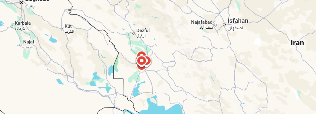
Target Formation: Deep HPHT Khami Sour Gas Carbonates (High Pressure, High H₂S & Narrow ECD Window)
Regional Cementing Background in Khuzestan Carbonate Plays
In the Ahwaz field of southwestern Iran, drilling operations penetrate overpressured gas-bearing carbonate reservoirs within the Cretaceous-Jurassic Khami Group. Well measured depths regularly exceed 4,900 to 5,300 meters (16,000 to 17,400 feet). Downhole conditions are severe: bottom-hole static temperatures (BHST) climb to 165°C to 175°C (329°F to 347°F) with formation pressures exceeding 12,000 psi (82.7 MPa). The formations produce high concentrations of sour gas (H₂S up to 6% and CO₂ up to 8%). Cementing 7-inch production liners across the Khami interval requires heavy Class G slurry systems (1.98 to 2.10 g/cm³) weighted with barite and stabilized by high-temperature polymers.
Regional Cementing Challenges in Extreme HPHT Formations
Operators cementing deep production liners across the Khami formation encounter critical technical hurdles:
- Severe Retarder Sensitivity: At temperatures above 160°C, minor variations of 0.05% BWOC in chemical retarder concentration cause large swings in thickening time, risking premature flash setting or multi-day setting delays.
- Narrow Equivalent Circulating Density (ECD) Windows: Close margins between formation pore pressure and fracture breakdown pressure demand low-viscosity slurries that maintain steady rheology without premature gelation spikes.
- Risk of Sour Gas Channeling: An extended transition time during slurry phase changes allows sour gas invasion into the decaying hydrostatic column, creating sustained casing pressure (SCP).
Technical Requirements for Slurry Qualification
To qualify a heavy 1.98 g/cm³ (16.5 ppg) Class G cement system across the Khami gas zone, the operator established strict performance criteria:
- Thickening time validation on an HPHT consistometer confirming a pumpability window of 5 hours and 30 minutes to 70 Bc under simulated dynamic ramp schedules.
- API fluid loss control strictly below 35 mL/30 min at 165°C using an automated high-temperature fluid loss cell to prevent dehydration.
- Static gel strength (SGS) transition window (from 100 to 500 lbf/100 ft²) of less than 30 minutes, with 24-hour compressive strength exceeding 3,500 psi (24.1 MPa).
How Advanced Fluid Loss Technology Resolved the Field Challenge
To resolve these downhole uncertainties, the operator formulated a customized Class G slurry incorporating KELIOIL synthetic AMPS-copolymer salt-resistant fluid loss additives, high-temperature retarders, sulfonated dispersants, and 35% BWOC silica flour. The high charge density of the AMPS polymer maintained complete hydration in the high-temperature saline environment, establishing an impermeable filter cake across the porous carbonate faces that restricted API fluid loss to 32 mL/30 min at 165°C.
Consistometer test curves confirmed a stable thickening time of 5 hours and 38 minutes to 70 Bc with zero early viscosity peaking. During field execution at Well Ahwaz-412, the slurry was pumped across the 1,050-meter liner without surface pressure surges or ECD spikes. Post-job radial acoustic cement bond logs (CBL-VDL) confirmed 100% circumferential bonding across the Khami sour gas pay zone. Subsequent negative pressure testing recorded zero sustained annular pressure, proving that precision chemical control based on how does a fluid loss additive work in oilwell cementing provides the empirical foundation required to eliminate cementing failures in extreme HPHT plays.
Laboratory Testing Standards and Quality Control Protocols
Validating fluid loss additive performance requires standardized laboratory protocols adhering to API RP 10B-2 guidelines:
- High-Pressure High-Temperature (HPHT) Filter Press Testing: Slurry samples are conditioned in an atmospheric consistometer to bottom-hole circulating temperature (up to 88°C) or in an HPHT consistometer for higher temperatures, then transferred into an API stirred fluid loss cell. Differential nitrogen pressure of 1,000 psi (6.89 MPa) is applied across a certified 325-mesh (45-micron) stainless steel screen, and filtrate volume is collected at 30 seconds, 1 minute, 2 minutes, 5 minutes, 15 minutes, and 30 minutes.
- Testing with Actual Field Mix Water Batches: Dissolved salts, divalent calcium (Ca²⁺) and magnesium (Mg²⁺) ions, and pH variations in rig mix water alter polymer chain extension. Always test fluid loss additives using actual rig water samples rather than laboratory deionized water.
- Rheology and Compatibility Profiling: Measure plastic viscosity and yield point on rotational viscometers across 600, 300, 200, 100, 6, and 3 rpm. Verify that the fluid loss additive does not induce excessive slurry gelation or cause antagonistic flocculation when combined with dispersants.
- Free Fluid and Settling Checks: Conditioned slurry must be poured into a 250 mL glass cylinder and allowed to stand undisturbed at circulating temperature for 2 hours. Free fluid breakout must remain strictly below 1.0% (and 0.0% for gas-bearing intervals).
Frequently Asked Questions (FAQ) Regarding Fluid Loss Additives
1. What is the difference between fluid loss control and lost circulation control?
Fluid loss control refers to preventing the loss of aqueous filtrate through the microscopic pore network of permeable matrix formations via polymer filter cake deposition. Lost circulation control (LCM) involves mechanically bridging large subterranean fractures, vugs, or cavernous zones using coarse granular, flake, or fibrous bridging materials to stop the escape of whole cement slurry.
2. How does salt concentration in mix water affect fluid loss polymers?
High salt concentrations (such as seawater or saturated NaCl/KCl brines) compress the electrical double layer around ionic polymer chains, causing traditional cellulosic and polyacrylamide molecules to coil and lose water-binding efficiency. Synthetic AMPS polymers contain rigid sulfonate groups that maintain complete molecular extension in saturated brine, providing consistent filtration control.
3. What happens if a cement slurry is overdosed with fluid loss additives?
Overdosing fluid loss polymers can excessively increase slurry plastic viscosity, making the fluid difficult to mix and pump. In addition, high concentrations of synthetic polymers can coat clinker grains, excessively delaying hydration, extending thickening time, and retarding early compressive strength development.
Strategic Recommendations for Slurry Placement and Wellbore Integrity
In modern well construction, achieving permanent zonal isolation depends directly on empirical laboratory precision and chemical formulation science. Understanding how does a fluid loss additive work in oilwell cementing enables drilling and completion teams to prevent slurry dehydration, maintain hydrostatic pressure transmission, and eliminate gas channeling.
KELIOIL remains committed to manufacturing high-performance oilfield cementing additives under strict ISO 9001 and API Spec 10A quality control standards. By combining state-of-the-art polymer synthesis with comprehensive laboratory testing support, KELIOIL provides operators and cementing service contractors worldwide with dependable fluid loss additives that guarantee wellbore integrity, protect the environment, and ensure long-term hydrocarbon asset productivity.
Optimize Your Slurry Filtration Control with KELIOIL Additives
Our technical chemical specialists provide customized slurry formulation designs, API Spec 10A laboratory testing verification, and reliable bulk supply of premium cementing additives tailored to demanding onshore and offshore drilling operations.