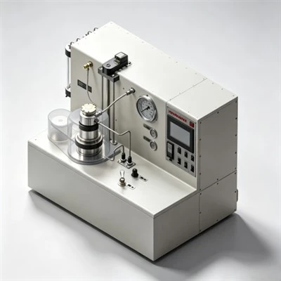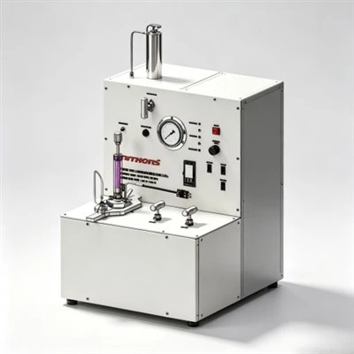

When petroleum laboratory chemists evaluate what happens when too much fluid loss additive is used, they analyze the severe operational penalties of chemical overdosing, which include excessive plastic viscosity surges, unstable yield points, uncontrolled hydration retardation, and reduced set-cement compressive strength across complex wells in the Middle East, the Gulf of Mexico, and the Tarim Basin. Exploring what happens when too much fluid loss additive is used reveals that while adequate filtration control prevents formation water loss, excess polymeric molecules encapsulate unhydrated clinker minerals, impair water mobility, and drastically elevate equivalent circulating density (ECD) beyond formation breakdown limits. By evaluating what happens when too much fluid loss additive is used through standardized API Spec 10A and API RP 10B-2 laboratory protocols, cementing engineers establish optimal dosage windows that control filtration below 50 mL/30 min without risking premature annular flash gelation or prolonged waiting-on-cement (WOC) rig delays.

The Operational Paradox of Over-Treating Oilfield Cement Slurries
In petroleum well construction, primary cementing represents the critical barrier designed to anchor casing strings, isolate permeable hydrocarbon zones, prevent cross-flow into freshwater aquifers, and protect steel pipe from corrosive downhole fluids such as hydrogen sulfide (H₂S) and carbon dioxide (CO₂). To ensure that cement slurry can be pumped to planned depths without premature desiccation, filtration control additives are routinely introduced into the mix water. However, an operational misconception in field cementing suggests that adding more chemical additive provides an extra safety margin.
In reality, oilfield cement slurries are highly sensitive colloidal suspensions governed by delicate physical and chemical equilibria. When high-molecular-weight fluid loss control agents-such as synthetic AMPS copolymers, modified cellulose ethers, or natural biopolymers-are overdosed, the rheological and setting characteristics of the slurry degrade rapidly. The excess polymer chains entangle within the aqueous phase, causing plastic viscosity and Bingham yield point to surge well beyond pumpable limits.
This dramatic rise in flow resistance elevates surface pumping pressures and surges equivalent circulating density (ECD) downhole. In narrow annular geometries, the resulting pressure spikes easily exceed the formation fracture breakdown gradient, triggering severe lost circulation. Furthermore, excess polymer molecules adsorb heavily onto unhydrated clinker surfaces, blocking water contact and delaying hydration kinetics. Evaluating what happens when too much fluid loss additive is used allows drilling and completion engineers to recognize the warning signs of chemical over-treatment, ensuring balanced slurry formulations that protect both wellbore integrity and rig economics.
1. Mechanism of Hydration Retardation and Thickening Time Extension
Portland cement hydration is a dissolution-precipitation reaction driven primarily by tricalcium silicate (C₃S) and tricalcium aluminate (C₃A). Under normal conditions, mix water dissolves surface calcium ions (Ca²⁺) and hydroxide ions (OH⁻), supersaturating the aqueous pore solution and precipitating interlocking calcium silicate hydrate (C-S-H) gel fibers.
When fluid loss additives are overdosed, their long-chain macromolecules accumulate in high concentrations at the solid-liquid interface. The polar functional groups-such as sulfonate (–SO₃⁻), carboxylate (–COO⁻), and hydroxyl (–OH) groups-adsorb extensively across the positive and negative coordination sites of unhydrated cement grains. This dense polymer coating creates a physical and electrostatic barrier that restricts water diffusion to clinker minerals, dramatically suppressing the dissolution rate of C₃S.
As a direct result, the dormant induction period is artificially extended. While this prolongs pumpability, severe overdosing causes the slurry to remain fluid or weakly gelled for 24 to 48 hours. This prolonged transition period allows hydrostatic pressure transmission to decay, leaving the wellbore vulnerable to formation gas invasion and creating sustained casing pressure (SCP) at the surface.
2. Rheological Deterioration: Severe Viscosity and Yield Point Surges
Fluid loss additives inherently increase the micro-viscosity of the aqueous phase to reduce filtrate velocity through compacted filter cakes according to Darcy's law. At recommended concentrations (typically 0.3% to 0.8% BWOC for synthetics), this viscosification is manageable and can be balanced using chemical dispersants.
However, when excessive additive is introduced, polymer chains overlap and form interconnected physical networks throughout the slurry body. This excessive entanglement drastically elevates plastic viscosity (PV) and Bingham yield point (YP). The slurry transitions from a workable, fluid suspension into a thick, paste-like gel. On the rig floor, such slurries resist mixing in recirculating cementing mixers, cavitate triplex charge pumps, and generate extreme friction losses inside casing tubulars. The resulting equivalent circulating density (ECD) spikes risk fracturing exposed formations, leading to lost circulation and cementing failure.
Laboratory Rheological Profiling Under Incremental Additive Loadings
To demonstrate the direct consequences of overdosing, laboratory rotational viscometer tests evaluate slurry properties under varying concentrations of synthetic AMPS fluid loss additives:
The experimental data highlights a clear point of diminishing returns: while increasing dosage from 0.5% to 1.4% reduces fluid loss marginally from 42 mL to 26 mL, it causes plastic viscosity to more than double (from 45 to 95 mPa·s) and drives the yield point to an unacceptable 40 lbf/100 ft².
3. Mechanical Degradation of Set Cement Compressive Strength
A set cement sheath must develop sufficient mechanical compressive and tensile strength to withstand casing pressure testing, drilling vibrations, and hydraulic fracturing stimulation. Excessive fluid loss additive loadings can directly impair set cement microstructure:
- Interrupted Crystal Interlocking: Hydrating cement derives its mechanical strength from interlocking crystalline networks of needle-like ettringite and fibrillar C-S-H gel. Heavy polymer coatings interfere with crystal coalescence, leaving weak amorphous zones within the set matrix.
- Pore Space Obstruction: High polymer concentrations remain trapped within capillary pore networks. Over time, unreacted polymer chains can degrade or leave spongy, compressible residues that reduce the ultimate modulus of elasticity and lower compressive strength by 20% to 35%.
- Interfacial Micro-Annuli Formation: Slurries overdosed with polymers exhibit altered autogenous shrinkage profiles during setting. Incomplete hydration crystal bonding against casing steel can lead to microscopic debonding, resulting in poor bond logs (CBL-VDL) and potential annular leak paths.
4. Comprehensive Comparison: Correct Dosage vs. Overdosed Slurry Systems
To assist operational teams in identifying chemical over-treatment, the table below compares key technical properties between an optimized slurry formulation and an overdosed system:
Regional Application Case: Deep Carbonate Sour Gas Production Liner Cementing in the Ahwaz Field, Khuzestan Province, Iran
Case Application: Ahwaz Oilfield, Khuzestan Province, Southwestern Iran

Target Formation: Deep HPHT Khami Sour Gas Carbonates (High Pressure, High H₂S & Narrow ECD Window)
Regional Cementing Background in Khuzestan Carbonate Plays
In the Ahwaz field of southwestern Iran, drilling operations penetrate overpressured gas-bearing carbonate reservoirs within the Cretaceous-Jurassic Khami Group. Well measured depths regularly exceed 4,900 to 5,300 meters (16,000 to 17,400 feet). Downhole conditions are severe: bottom-hole static temperatures (BHST) climb to 165°C to 175°C (329°F to 347°F) with formation pressures exceeding 12,000 psi (82.7 MPa). The formations produce sour gas containing H₂S (up to 6%) and CO₂ (up to 8%). Cementing 7-inch production liners across the Khami interval requires heavy Class G slurry systems (1.98 to 2.10 g/cm³) weighted with barite and stabilized by high-temperature polymers.
Regional Cementing Challenges in Extreme HPHT Formations
Operators cementing deep production liners across the Khami formation encounter critical technical hurdles:
- Severe Retarder Sensitivity: At temperatures above 160°C, minor variations of 0.05% BWOC in chemical retarder concentration cause large swings in thickening time, risking premature flash setting or multi-day setting delays.
- Narrow Equivalent Circulating Density (ECD) Windows: Close margins between formation pore pressure and fracture breakdown pressure demand low-viscosity slurries that maintain steady rheology without premature gelation spikes.
- Risk of Sour Gas Channeling: An extended transition time during slurry phase changes allows sour gas invasion into the decaying hydrostatic column, creating sustained casing pressure (SCP).
Technical Requirements for Slurry Qualification
To qualify a heavy 1.98 g/cm³ (16.5 ppg) Class G cement system across the Khami gas zone, the operator established strict performance criteria:
- API fluid loss control strictly below 35 mL/30 min at 165°C using an automated high-temperature stirred fluid loss cell to prevent dehydration.
- Thickening time validation on an HPHT consistometer confirming a pumpability window of 5 hours and 30 minutes to 70 Bc under simulated dynamic ramp schedules.
- Static gel strength (SGS) transition window (from 100 to 500 lbf/100 ft²) of less than 30 minutes, with 24-hour compressive strength exceeding 3,500 psi (24.1 MPa).
How Resolving Overdosing Risks Ensured Zonal Isolation
During initial laboratory design for Well Ahwaz-412, technicians evaluated what happens when too much fluid loss additive is used in heavy barite-weighted slurries. In an attempt to drive fluid loss below 25 mL, chemists overdosed the system with 2.4% BWOC synthetic fluid loss polymer. While fluid loss reached 22 mL, the slurry's plastic viscosity soared to 68 mPa·s with a yield point of 38 lbf/100 ft². Consistometer testing revealed severe sluggish setting, extending pumpability to over 7 hours and delaying 500 psi compressive strength development to 26 hours. Hydraulic modeling indicated that pumping this overdosed formulation would breach the formation fracture gradient by 0.6 ppg ECD, risking severe lost circulation.
Recognizing the failure risks of chemical over-treatment, the laboratory re-engineered the formulation. By reducing KELIOIL synthetic AMPS salt-resistant fluid loss additive to an optimized 1.8% BWOC and balancing it with high-temperature synthetic retarders, sulfonated dispersants, and 35% BWOC silica flour, the slurry achieved an API fluid loss of 32 mL/30 min at 165°C while plastic viscosity dropped to 38 mPa·s. Consistometer testing confirmed an ideal right-angle set profile with an exact thickening time of 5 hours and 38 minutes to 70 Bc, while ultrasonic testing verified 500 psi strength development in 9 hours and 24-hour strength exceeding 3,800 psi.
During wellsite execution, the balanced slurry was pumped across the 1,050-meter liner without surface pressure surges or ECD spikes. Post-job radial acoustic cement bond logs (CBL-VDL) confirmed 100% circumferential bonding across the Khami sour gas pay zone. Subsequent negative pressure testing recorded zero sustained annular pressure, proving that understanding what happens when too much fluid loss additive is used provides the empirical precision required to eliminate cementing failures in extreme HPHT plays.
Economic and Risk Implications of Chemical Overuse
Overdosing fluid loss control chemicals carries both direct financial and operational costs:
- Inflated Chemical Expenditure: Synthetic AMPS-copolymer and latex additives represent specialty chemical investments. Over-treating bulk slurries by 30% to 50% increases chemical costs without delivering tangible technical value.
- Rig Waiting-on-Cement (WOC) Costs: When overdosing delays cement hydration, drilling operations cannot resume until the casing shoe develops regulatory compressive strength (typically 500 to 1,000 psi). Extending WOC by 12 to 24 hours on offshore drillships inflates spread costs by hundreds of thousands of dollars.
- Catastrophic Remedial Squeeze Cementing: If an overdosed slurry breaks down a weak formation and induces lost circulation, the top of cement will fall below target depths. Repairing an incomplete cement sheath requires casing perforation and remedial squeeze cementing, generating substantial non-productive time (NPT).
Frequently Asked Questions (FAQ) Regarding Fluid Loss Additive Overdosing
1. What is the fastest way to detect an overdosed slurry in the field?
The earliest field indicator of an overdosed slurry is high mixing resistance in the recirculating cement mixer, accompanied by elevated surface manifold pressures during initial casing injection. If rotational viscometer readings taken on the rig floor show plastic viscosity exceeding 60 to 70 mPa·s before pumping commences, the slurry is likely over-treated.
2. Can adding extra dispersant correct an overdosed fluid loss additive formulation?
While adding dispersant can temporarily lower plastic viscosity by deflocculating cement clusters, it does not resolve polymer-induced hydration retardation. Furthermore, overdosing dispersants can displace fluid loss polymers from mineral grain surfaces, degrading the filter cake and causing fluid loss to surge. Chemical balancing must be conducted in the laboratory rather than through uncalibrated field additions.
3. Why does overdosing fluid loss additives increase gas migration risks?
Overdosed slurries exhibit extended, sluggish setting behavior where static gel strength develops slowly from 100 to 500 lbf/100 ft². During this prolonged period, the cement column supports its own weight and hydrostatic pressure transmission decays, giving formation gas an extended window to invade the setting slurry and create continuous micro-channels.
Strategic Recommendations for Slurry Formulation and Quality Assurance
Achieving dependable zonal isolation requires striking a precise balance between fluid loss control, slurry rheology, and hydration kinetics. Understanding what happens when too much fluid loss additive is used allows drilling engineers and laboratory specialists to formulate optimized cement slurries that maintain pumpability, protect weak formations from hydraulic breakdown, and achieve high compressive strength.
KELIOIL remains dedicated to manufacturing high-performance oilfield cementing additives under strict ISO 9001 and API Spec 10A quality control standards. By integrating advanced polymer synthesis with comprehensive laboratory testing support, KELIOIL empowers operators and service contractors worldwide to optimize chemical additive dosages, eliminate downhole cementing failures, and ensure lifelong well integrity across demanding energy frontiers.
Optimize Your Slurry Formulations with KELIOIL Fluid Loss Additives
Our technical chemical specialists provide customized slurry dosage optimization, API Spec 10A laboratory testing verification, and reliable bulk supply of premium cementing additives tailored to demanding onshore and offshore drilling operations.