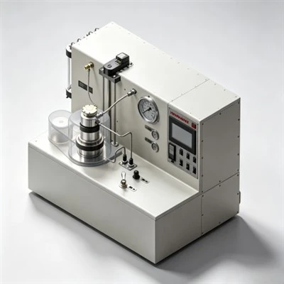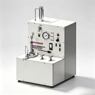

When cementing engineers evaluate how to optimize the dosage of a fluid loss additive, they establish an empirical balancing workflow that correlates API filtration limits with slurry plastic viscosity, Bearden consistency (Bc) curves, and setting kinetics across challenging reservoirs in the Middle East, the Gulf of Mexico, and the Tarim Basin. Determining how to optimize the dosage of a fluid loss additive is vital because under-dosing leads to rapid filtrate invasion, premature slurry dehydration, and high equivalent circulating density (ECD) surges, whereas overdosing can induce excessive plastic viscosity, severe chemical retardation, and extended waiting-on-cement (WOC) downtime. By executing multi-concentration pilot evaluations to optimize the dosage of a fluid loss additive in compliance with API Spec 10A and API RP 10B-2 testing standards, laboratory specialists identify the exact concentration threshold that maintains filtration below 50 mL/30 min while preserving smooth slurry pumpability and gas-tight zonal isolation.

The Operational Imperative of Precision Dosage in Primary Well Cementing
In petroleum exploration and well construction, primary cementing represents the primary physical barrier that anchors casing tubulars, isolates permeable hydrocarbon zones, protects shallow potable water aquifers from cross-contamination, and shields tubular steel from corrosive downhole brines. However, displacing a cement slurry down casing tubulars and up into the subterranean annulus exposes the fluid to severe thermodynamic, barometric, and lithological gradients. Bottom-hole circulating temperatures (BHCT) frequently exceed 150°C to 180°C, with confining hydrostatic pressures surpassing 80 to 120 MPa (11,600 to 17,400 psi).
Across permeable sandstone and carbonate formations, the hydrostatic pressure of the cement column exceeds formation pore pressure. Under this differential pressure gradient, aqueous mix water escapes into the rock matrix. If chemical water retention is inadequate, rapid filtration alters the designed water-to-cement ratio. Cement clinker particles pack tightly together, causing slurry viscosity to surge. This premature dehydration triggers friction spikes that drive equivalent circulating density (ECD) beyond formation fracture breakdown limits, inducing severe lost circulation and leaving casing assemblies stuck off-bottom.
Conversely, adding excessive chemical additives introduces new operational complications. Overdosing polymeric fluid loss reducers elevates plastic viscosity and Bingham yield point, making the slurry difficult to mix on the rig floor and pump through surface lines. In addition, excess polymer chains encapsulate clinker mineral grains-specifically tricalcium silicate (C₃S)-retarding hydration kinetics and delaying compressive strength development. This operational trade-off illustrates why engineers must systematically optimize the dosage of a fluid loss additive. Through controlled laboratory screening, technical teams identify the exact concentration that provides robust filtration control without sacrificing rheological stability or inflating operational costs.
1. Downhole Factors Determining Chemical Dosage Requirements
The concentration of fluid loss additive required for a specific wellbore cannot be determined by static rule-of-thumb estimates. Laboratory chemists must adjust additive volumes based on five critical wellbore parameters:
- Bottom-Hole Circulating Temperature (BHCT): Elevated temperatures accelerate water mobility and can cause thermal degradation of organic polymer backbones. As circulating temperatures rise above 120°C, higher additive concentrations or advanced AMPS-based synthetic copolymers are required to maintain a durable filter cake.
- Differential Hydrostatic Overbalance: The pressure differential between the annular cement column and formation pore pressure provides the mechanical driving force for filtrate loss. Wellbores with high hydrostatic overbalance require higher polymer concentrations to build compact, low-permeability filter cakes.
- Formation Permeability and Pore Throat Distribution: Coarse, unconsolidated sandstones absorb water rapidly and require higher additive loadings to establish polymer bridging, whereas tight, low-permeability shales require lower chemical concentrations.
- Mix-Water Salinity and Cationic Composition: High concentrations of monovalent sodium (Na⁺) and divalent calcium (Ca²⁺) ions compress the electrical double layer around ionic polymer chains. Salt-saturated or seawater systems demand salt-tolerant sulfonated polymers at adjusted concentrations to overcome cationic screening.
- Slurry Density and Solids Volume Fraction: High-density slurries weighted with barite or hematite naturally possess higher solid surface areas that adsorb polymer chains. Conversely, extended lightweight slurries containing hollow glass microspheres require precise dosing to avoid over-viscosification.
2. Typical Dosage Ranges Across Major Additive Chemistries
Fluid loss additives exhibit varying chemical activity levels, active solid contents, and molecular weights. The table below outlines typical operational dosage ranges across primary chemical families, expressed as percentage by weight of cement (% BWOC) or gallons per sack (gal/sk) for liquid formulations:
3. Laboratory Optimization Protocols: Evaluating Iterative Test Data
The primary engineering method to optimize the dosage of a fluid loss additive relies on conducting progressive pilot tests in an API-certified cementing laboratory. Technicians prepare slurry batches using actual rig mix water and representative Class G or Class H cement samples. By evaluating additive concentrations across an incremental spectrum (e.g., 0.3%, 0.5%, and 0.7% BWOC), laboratory teams generate performance curves that identify the optimal concentration threshold.
The table below presents a typical laboratory optimization dataset evaluating a high-density Class G cement slurry under HPHT conditions (140°C BHCT and 1,000 psi differential pressure):
As demonstrated in the evaluation matrix, increasing dosage from 0.3% to 0.5% BWOC achieves a sharp reduction in fluid loss from 180 mL down to 42 mL, successfully meeting API criteria. However, increasing dosage further to 0.7% BWOC yields diminishing filtration returns while increasing plastic viscosity by over 60%, elevating frictional pressure drop during annular placement. Identifying this point of diminishing returns represents the core objective when engineers optimize the dosage of a fluid loss additive.
4. Balancing Thickening Time and Compressive Strength Development
A critical operational challenge when adjusting fluid loss additive concentrations is managing the impact on cement hydration kinetics. Fluid loss polymers adsorb onto the surfaces of hydrating clinker minerals, acting as a physical barrier that restricts water access to unhydrated mineral cores.
Consequently, an increase in fluid loss additive dosage often lengthens thickening time. If the laboratory chemist fails to monitor this interaction, an overdosed slurry can remain in a fluid or gelled state long after placement is complete. This extended static gel transition window allows formation gas to permeate the setting cement column, generating sustained casing vent flow. Furthermore, delayed hydration slows early compressive strength development, forcing the drilling rig into prolonged waiting-on-cement downtime. Technicians must conduct continuous acoustic monitoring on an Ultrasonic Cement Analyzer (UCA) to verify that the slurry reaches 500 psi (3.45 MPa) compressive strength within 12 to 16 hours.
5. Chemical Compatibility: Balancing Fluid Loss Additives with Dispersants
Fluid loss additives function in synergy with chemical dispersants (friction reducers). When high-molecular-weight fluid loss polymers dissolve into mix water, their long molecular chains increase plastic viscosity. To maintain pumpability at practical surface pressures, engineers introduce sulfonated naphthalene formaldehyde (SNF) or polycarboxylate ether (PCE) dispersants to deflocculate cement clusters.
However, chemical balancing is delicate. Dispersants work by charging particle surfaces negatively, promoting electrostatic repulsion. If dispersant dosage is excessive, the dispersant molecules outcompete fluid loss polymers for adsorption sites on clinker faces, stripping the protective polymer layer and impairing filter cake integrity. Testing multi-additive combinations on rotational viscometers across 600, 300, 200, 100, 6, and 3 rpm ensures that the slurry achieves laminar flow without triggering solids settling or free fluid breakout.
Regional Application Case: Deep Carbonate Sour Gas Production Liner Cementing in the Ahwaz Field, Khuzestan Province, Iran
Case Application: Ahwaz Oilfield, Khuzestan Province, Southwestern Iran

Target Formation: Deep HPHT Khami Sour Gas Carbonates (High Pressure, High H₂S & Narrow ECD Window)
Regional Cementing Background in Khuzestan Carbonate Plays
In the Ahwaz field of southwestern Iran, drilling operations penetrate overpressured gas-bearing carbonate reservoirs within the Cretaceous-Jurassic Khami Group. Well measured depths regularly exceed 4,900 to 5,300 meters (16,000 to 17,400 feet). Downhole conditions are severe: bottom-hole static temperatures (BHST) climb to 165°C to 175°C (329°F to 347°F) with formation pressures exceeding 12,000 psi (82.7 MPa). The formations produce sour gas containing H₂S (up to 6%) and CO₂ (up to 8%). Cementing 7-inch production liners across the Khami interval requires heavy Class G slurry systems (1.98 to 2.10 g/cm³) weighted with barite and stabilized by high-temperature polymers.
Regional Cementing Challenges in Extreme HPHT Formations
Operators cementing deep production liners across the Khami formation encounter critical technical hurdles:
- Severe Retarder Sensitivity: At temperatures above 160°C, minor variations of 0.05% BWOC in chemical retarder concentration cause large swings in thickening time, risking premature flash setting or multi-day setting delays.
- Narrow Equivalent Circulating Density (ECD) Windows: Close margins between formation pore pressure and fracture breakdown pressure demand low-viscosity slurries that maintain steady rheology without premature gelation spikes.
- Risk of Sour Gas Channeling: An extended transition time during slurry phase changes allows sour gas invasion into the decaying hydrostatic column, creating sustained casing pressure (SCP).
Technical Requirements for Slurry Qualification
To qualify a heavy 1.98 g/cm³ (16.5 ppg) Class G cement system across the Khami gas zone, the operator established strict performance criteria:
- API fluid loss control strictly below 35 mL/30 min at 165°C using an automated high-temperature stirred fluid loss cell to prevent dehydration.
- Thickening time validation on an HPHT consistometer confirming a pumpability window of 5 hours and 30 minutes to 70 Bc under simulated dynamic ramp schedules.
- Static gel strength (SGS) transition window (from 100 to 500 lbf/100 ft²) of less than 30 minutes, with 24-hour compressive strength exceeding 3,500 psi (24.1 MPa).
How Laboratory Dosage Optimization Resolved the Field Challenge
To resolve these downhole uncertainties, the operator's central laboratory executed a systematic screening matrix to optimize the dosage of a fluid loss additive. Initial formulation trials tested KELIOIL synthetic AMPS salt-resistant fluid loss additives at 1.2%, 1.8%, and 2.4% BWOC. At 1.2% BWOC, fluid loss reached 68 mL/30 min, failing gas-tight specifications. At 2.4% BWOC, the slurry exhibited high plastic viscosity (64 mPa·s), which surged calculated annular ECD beyond allowable formation limits.
The laboratory identified 1.8% BWOC as the optimal dosage point. Paired with high-temperature synthetic retarders, sulfonated dispersants, and 35% BWOC silica flour, the 1.8% formulation delivered an API filtration rate of 32 mL/30 min at 165°C while maintaining plastic viscosity at 38 mPa·s. Consistometer testing confirmed an ideal right-angle set profile with an exact thickening time of 5 hours and 38 minutes to 70 Bc.
During field execution at Well Ahwaz-412, the slurry was mixed continuously and displaced across the 1,050-meter liner without surface pressure surges or ECD spikes. Subsequent radial acoustic cement bond logs (CBL-VDL) confirmed 100% circumferential bonding across the Khami sour gas pay zone. Negative pressure testing recorded zero sustained annular casing pressure, proving that precision laboratory testing to optimize the dosage of a fluid loss additive provides the empirical foundation required to eliminate cementing failures in extreme HPHT plays.
Seven-Step Standardized Workflow for Field Dosage Optimization
To ensure repeatable field results and avoid chemical over-treatment, cementing engineering teams follow a standardized seven-stage optimization procedure:
- Collect Wellbore Operational Data: Establish bottom-hole circulating temperature (BHCT), bottom-hole static temperature (BHST), pore and fracture pressure gradients, and planned casing displacement durations.
- Sample Rig-Specific Materials: Obtain representative field samples of delivered Class G or Class H dry cement and actual rig batch mix water, avoiding laboratory deionized water.
- Select Baseline Additive Chemistry: Select the appropriate chemical backbone (PVA for low temperatures, AMPS terpolymers for HPHT, or latex for gas wells).
- Conduct Multi-Concentration Pilot Testing: Prepare three slurry batches spanning the anticipated concentration spectrum (low, medium, high) and measure API fluid loss under downhole temperature and pressure.
- Evaluate Rheology and Thickening Time: Measure plastic viscosity, yield point, and consistometer pumpability curves to 70 Bc for each dosage level.
- Select Economic Optimum Dosage: Identify the lowest concentration that reliably satisfies API fluid loss targets while preserving acceptable rheology and a 90 to 120-minute thickening safety margin.
- Conduct Final Job Confirmation Tests: Run a complete confirmatory slurry test incorporating all primary additives (retarders, dispersants, defoamers) before approving the field pumping schedule.
Frequently Asked Questions (FAQ) Regarding Fluid Loss Additive Dosage Optimization
1. What are the operational indicators of an under-dosed fluid loss additive in the field?
Field signs of an under-dosed fluid loss additive include sudden surface pumping pressure increases during displacement, higher-than-expected fluid returns indicating dehydration bridging, premature slurry gelation inside the annulus, and failure to establish the planned top of cement (TOC) due to filtrate leak-off into permeable thief zones.
2. How does mix-water quality influence the required fluid loss additive dosage?
Dissolved hardness ions (divalent Ca²⁺ and Mg²⁺) and high chloride concentrations screen electrostatic charges on ionic polymer molecules, reducing their hydration volume. If mix water shifts from fresh municipal water to brackish drill water or seawater, fluid loss additive dosage must typically be increased by 20% to 40% (or switched to salt-tolerant AMPS copolymers) to achieve equivalent filtration control.
3. Can increasing fluid loss additive dosage compensate for poor borehole mud removal?
No. Fluid loss additives control water filtration from the cement slurry into permeable formations. They cannot remove gelled drilling mud cakes or reverse oil-wet casing surfaces. Effective mud removal requires engineered chemical washes, weighted spacers, and mechanical casing centralization pumped ahead of the cement slurry.
Strategic Chemical Selection for Reliable Wellbore Zonal Isolation
In modern well construction, achieving permanent zonal isolation depends directly on empirical laboratory precision and chemical formulation science. Understanding how to optimize the dosage of a fluid loss additive enables drilling and completion teams to prevent slurry dehydration, maintain hydrostatic pressure transmission, and eliminate gas channeling.
KELIOIL remains committed to manufacturing high-performance oilfield cementing additives under strict ISO 9001 and API Spec 10A quality control standards. By combining state-of-the-art polymer synthesis with comprehensive laboratory testing support, KELIOIL provides operators and cementing service contractors worldwide with dependable fluid loss additives that guarantee wellbore integrity, protect the environment, and ensure long-term hydrocarbon asset productivity.
Optimize Your Slurry Filtration Control with KELIOIL Additives
Our technical chemical specialists provide customized slurry formulation designs, API Spec 10A laboratory testing verification, and reliable bulk supply of premium cementing additives tailored to demanding onshore and offshore drilling operations.