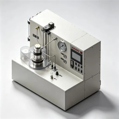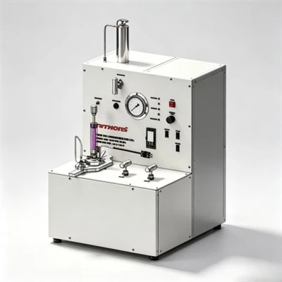

When petroleum cementing chemists evaluate how does a fluid loss additive affect thickening time, they analyze how water retention, clinker mineral surface adsorption, and polymer-retarder competitive interactions alter the hydration kinetics of Portland cement across deep wellbores in the Middle East, the Gulf of Mexico, and the Tarim Basin. Exploring how does a fluid loss additive affect thickening time demonstrates that while maintaining the design water-to-cement ratio prevents mechanical slurry dehydration and premature friction spikes, certain high-molecular-weight synthetic polymers and modified celluloses can retard tricalcium silicate (C₃S) dissolution, extending pumpability windows beyond planned schedules. By applying testing protocols structured around how does a fluid loss additive affect thickening time in compliance with API Spec 10A and API RP 10B-2, engineers balance chemical dosages on HPHT consistometers, establish an engineered placement safety buffer, prevent downhole flash setting, and preserve long-term annular zonal isolation.

The Operational Interdependence of Filtration Control and Thickening Time
In petroleum well construction, primary cementing serves as the foundational barrier that anchors casing strings, isolates permeable hydrocarbon zones, protects shallow freshwater aquifers from cross-contamination, and shields casing steel from corrosive formation fluids. Once mixed at surface, cement slurry is displaced down casing tubulars and upward into the subterranean annulus. Throughout this dynamic displacement, the slurry column exerts hydrostatic pressure that exceeds the pore pressure of adjacent porous rock formations.
This pressure overbalance drives aqueous mix water out of the slurry and into the formation. If filtration is uncontrolled, the rapid loss of water concentrates solid clinker particles, causing apparent viscosity to surge. This premature dehydration triggers bridging across casing collars and narrow annular spaces, driving equivalent circulating density (ECD) beyond formation fracture breakdown limits. Pumping pressures spike, inducing severe lost circulation and leaving casing assemblies stuck off-bottom.
To prevent dehydration, engineers introduce fluid loss control additives. However, adding high-molecular-weight polymers introduces complex chemical interactions that directly influence thickening time. Examining how does a fluid loss additive affect thickening time reveals a two-fold chemical mechanism: retaining free mix water maintains the fluid phase and dilutes solid hydration products, while polymer chain adsorption onto clinker surfaces can shield mineral grains from water contact, altering the dormant induction period. Understanding these interactions allows engineers to adjust retarder and dispersant concentrations, ensuring the slurry remains pumpable throughout displacement without causing excessive wait-on-cement (WOC) downtime.
1. Fluid Loss Control and Hydration Kinetics: The Mechanism of Setting Alteration
To analyze how does a fluid loss additive affect thickening time, one must examine the hydration kinetics of Portland cement clinker minerals, specifically tricalcium silicate (C₃S) and tricalcium aluminate (C₃A). When cement hydrates, dissolution of calcium ions (Ca²⁺) and hydroxide ions (OH⁻) into the pore solution leads to the precipitation of interlocking calcium silicate hydrate (C-S-H) gel fibers.
When an effective fluid loss additive maintains the designed water-to-cement ratio, the volume of continuous aqueous phase remains stable. This liquid buffer separates hydrating clinker grains, slowing down the percolation threshold where C-S-H fibers interlock into a rigid structural matrix. Consequently, low fluid loss extends the measured thickening time. In contrast, high fluid loss drains interstitial water into permeable formations, concentrating clinker solids and accelerating mechanical gelation, which drastically shortens measured pumpability.
Correlation Between Fluid Loss Control and Thickening Behavior
2. Chemical Polymer Classes and Their Impact on Setting Profiles
Different chemical classes of fluid loss additives exhibit distinct effects on cement thickening curves:
1. Synthetic AMPS Copolymers and Terpolymers
Synthetic 2-acrylamido-2-methylpropane sulfonic acid (AMPS) copolymers are engineered for high-temperature stability up to 230°C. In addition to creating an impermeable filter cake, the anionic sulfonate groups (–SO₃⁻) interact with multivalent cations in the pore fluid. This moderate chelation provides a secondary retarding effect, lengthening thickening time in a predictable, linear manner.
2. Cellulose Derivatives (HEC and CMHEC)
Carboxymethyl hydroxyethyl cellulose (CMHEC) and hydroxyethyl cellulose (HEC) control fluid loss by viscosifying the aqueous phase. While HEC exhibits minimal chemical retardation, carboxymethyl groups in CMHEC adsorb onto hydrating clinker faces, extending thickening time at low to moderate temperatures.
3. Styrene-Butadiene Rubber (SBR) Latex Emulsions
Latex emulsions consist of sub-micron polymer spheres suspended in water. As filtrate is lost, the latex particles coalesce into a continuous elastomeric membrane. Because latex functions primarily through physical pore plugging rather than molecular dissolution, it exhibits neutral setting characteristics, having minimal impact on base thickening times while providing gas migration resistance.
4. Non-Retarding Polyvinyl Alcohol (PVA) Systems
In shallow surface casing jobs or cold-water marine environments, extending thickening time is undesirable because it inflates wait-on-cement time. Chemically modified PVA additives provide filtration control without adsorbing strongly onto C₃S grains, preserving rapid early compressive strength development.
Polymer Type and Thickening Time Behavior
3. Temperature Sensitivity and Additive Compatibility Dynamics
Temperature accelerates chemical reaction rates according to the Arrhenius relationship. In deep wells where bottom-hole circulating temperatures (BHCT) exceed 140°C to 180°C, mineral dissolution accelerates, compressing the thickening time window. If a fluid loss additive begins to degrade thermally, filtrate escapes rapidly, compounding thermal acceleration with physical dehydration and causing premature slurry flash setting.
Furthermore, fluid loss additives do not function in isolation; they interact with retarders and dispersants in the slurry pore water:
- Competitive Adsorption with Retarders: Both high-molecular-weight fluid loss polymers and synthetic retarders compete for adsorption sites on unhydrated C₃S and C₃A surfaces. When paired with AMPS polymers, retarder efficiency often increases, requiring chemists to optimize retarder dosage to avoid over-retarding the system.
- Dispersant Balancing: Polymeric dispersants (such as sulfonated naphthalene formaldehyde or polycarboxylates) deflocculate cement clusters to lower plastic viscosity. However, excessive dispersant can displace fluid loss polymers from mineral faces, reducing filtration control.
- Mix-Water Salinity Effects: In seawater or salt-saturated systems, monovalent and divalent cations screen polymer charges. Salt-tolerant AMPS polymers maintain extended chain conformation in brines, preventing unexpected thickening time shifts.
4. Laboratory Testing Protocols for Evaluating Setting Behavior
Because additive interactions are sensitive to mix-water chemistry and cement batch variations, laboratory validation under API RP 10B-2 standards is essential prior to wellsite pumping:
Regional Application Case: Deep Carbonate Sour Gas Production Liner Cementing in the Ahwaz Field, Khuzestan Province, Iran
Case Application: Ahwaz Oilfield, Khuzestan Province, Southwestern Iran

Target Formation: Deep HPHT Khami Sour Gas Carbonates (High Pressure, High H₂S & Narrow ECD Window)
Regional Cementing Background in Khuzestan Carbonate Plays
In the Ahwaz field of southwestern Iran, drilling operations penetrate overpressured gas-bearing carbonate reservoirs within the Cretaceous-Jurassic Khami Group. Well measured depths regularly exceed 4,900 to 5,300 meters (16,000 to 17,400 feet). Downhole conditions are severe: bottom-hole static temperatures (BHST) climb to 165°C to 175°C (329°F to 347°F) with formation pressures exceeding 12,000 psi (82.7 MPa). The formations produce sour gas containing H₂S (up to 6%) and CO₂ (up to 8%). Cementing 7-inch production liners across the Khami interval requires heavy Class G slurry systems (1.98 to 2.10 g/cm³) weighted with barite and stabilized by high-temperature polymers.
Regional Cementing Challenges in Extreme HPHT Formations
Operators cementing deep production liners across the Khami formation encounter critical technical hurdles:
- Severe Retarder Sensitivity: At temperatures above 160°C, minor variations of 0.05% BWOC in chemical retarder concentration cause large swings in thickening time, risking premature flash setting or multi-day setting delays.
- Narrow Equivalent Circulating Density (ECD) Windows: Close margins between formation pore pressure and fracture breakdown pressure demand low-viscosity slurries that maintain steady rheology without premature gelation spikes.
- Risk of Sour Gas Channeling: An extended transition time during slurry phase changes allows sour gas invasion into the decaying hydrostatic column, creating sustained casing pressure (SCP).
Technical Requirements for Slurry Qualification
To qualify a heavy 1.98 g/cm³ (16.5 ppg) Class G cement system across the Khami gas zone, the operator established strict performance criteria:
- API fluid loss control strictly below 35 mL/30 min at 165°C using an automated high-temperature stirred fluid loss cell to prevent dehydration.
- Thickening time validation on an HPHT consistometer confirming a pumpability window of 5 hours and 30 minutes to 70 Bc under simulated dynamic ramp schedules.
- Static gel strength (SGS) transition window (from 100 to 500 lbf/100 ft²) of less than 30 minutes, with 24-hour compressive strength exceeding 3,500 psi (24.1 MPa).
How Balancing Fluid Loss and Setting Kinetics Resolved the Field Challenge
To resolve these downhole uncertainties, the engineering team applied the principles of how does a fluid loss additive affect thickening time during laboratory formulation. Initial trials using cellulosic additives suffered thermal degradation, showing erratic thickening time curves with premature dehydration spikes. The laboratory re-engineered the formulation using KELIOIL synthetic AMPS-copolymer salt-resistant fluid loss additives (1.8% BWOC) paired with synthetic high-temperature retarders, sulfonated dispersants, and 35% BWOC silica flour.
Consistometer test curves confirmed a smooth right-angle set profile, maintaining a stable consistency of 18 Bc for 4 hours and 30 minutes before rising sharply to 70 Bc at 5 hours and 38 minutes. The AMPS additive preserved water retention (API fluid loss was 32 mL/30 min at 165°C) while working synergistically with the retarder. During field execution at Well Ahwaz-412, the slurry placed cleanly across the 1,050-meter liner without surface pressure anomalies or ECD spikes. Post-job radial acoustic cement bond logs (CBL-VDL) confirmed 100% circumferential bonding across the Khami sour gas pay zone. Subsequent negative pressure testing recorded zero sustained annular pressure, proving that precision chemical control based on how does a fluid loss additive affect thickening time provides the empirical foundation required to eliminate cementing failures in extreme HPHT plays.
Frequently Asked Questions (FAQ) Regarding Fluid Loss and Thickening Time
1. Why does poor fluid loss control cause sudden slurry flash setting?
When cement slurry loses water rapidly against porous formations, the solid clinker volume fraction increases beyond critical packing limits. Grains come into direct contact without lubricating water films, causing mechanical bridging and sudden consistency spikes that mimic chemical flash setting.
2. Can increasing fluid loss additive dosage replace chemical retarders?
No. While synthetic AMPS polymers provide moderate secondary retardation, they cannot replace dedicated high-temperature retarders. Relying solely on fluid loss polymers to extend thickening time leads to excessive plastic viscosity and poor slurry rheology. Retarders and fluid loss additives must be balanced in the laboratory.
3. What is the ideal consistometer curve profile for deep gas well cementing?
The ideal profile is a "right-angle set," where consistency remains flat and low (<25 Bc) throughout placement, followed by an abrupt transition from 30 Bc to 70 and 100 Bc in less than 15 minutes. This profile maximizes the safe pumping window while shortening the static gel strength transition to prevent gas channeling.
Strategic Recommendations for Slurry Placement and Wellbore Integrity
In modern well construction, achieving permanent zonal isolation depends directly on empirical laboratory precision and chemical formulation science. Understanding how does a fluid loss additive affect thickening time enables drilling and completion teams to formulate dependable slurries, optimize chemical additive packages, and eliminate downhole cementing failures.
KELIOIL remains committed to manufacturing high-performance oilfield cementing additives under strict ISO 9001 and API Spec 10A quality control standards. By combining state-of-the-art polymer synthesis with comprehensive laboratory testing support, KELIOIL provides operators and cementing service contractors worldwide with dependable fluid loss additives that guarantee wellbore integrity, protect the environment, and ensure long-term hydrocarbon asset productivity.
Optimize Your Slurry Thickening Times with KELIOIL Additives
Our technical chemical specialists provide customized slurry formulation designs, API Spec 10A laboratory testing verification, and reliable bulk supply of premium cementing additives tailored to demanding onshore and offshore drilling operations.