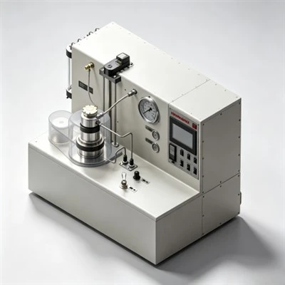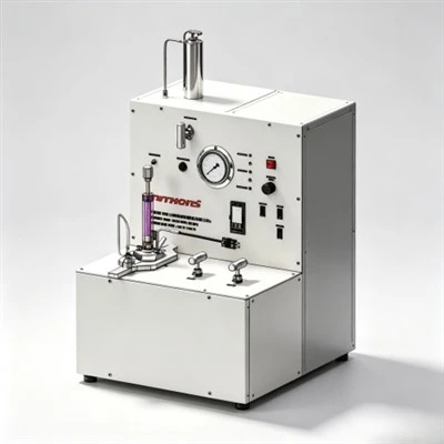

When petroleum laboratory specialists evaluate what tests measure fluid loss additive efficiency, they analyze standardized testing regimens-including ambient API filtration presses, high-pressure high-temperature (HPHT) stirred fluid loss cells, rotational viscometers, and atmospheric free-water cylinders-across complex energy plays in the Middle East, the Gulf of Mexico, and the Tarim Basin. Exploring what tests measure fluid loss additive efficiency reveals that evaluating chemical filtration reducers requires looking beyond simple 30-minute volume collections; technicians must assess dynamic filter cake compaction, plastic viscosity development, and early static gelation under simulated downhole geothermal schedules. By conducting comprehensive evaluations centered on what tests measure fluid loss additive efficiency in strict accordance with API Spec 10A and API RP 10B-2 standards, cementing teams identify optimal polymer formulations, prevent downhole slurry dehydration, eliminate micro-annular gas channeling, and secure lifelong wellbore zonal isolation.

The Operational Significance of Multi-Dimensional Filtration Diagnostics
In petroleum exploration and well construction, primary cementing represents the primary physical barrier required to anchor casing strings, prevent subsurface hydrocarbon cross-flow, protect shallow drinking water aquifers from contamination, and shield casing steel from corrosive subterranean fluids such as hydrogen sulfide (H₂S) and carbon dioxide (CO₂). Once cement slurry is pumped down casing tubulars and upward into the subterranean annulus, it enters an environment governed by steep geothermal and barometric gradients. Bottom-hole circulating temperatures (BHCT) frequently exceed 150°C to 180°C, accompanied by differential overbalance pressures surpassing 1,000 psi (6.89 MPa) against permeable geological strata.
Under this differential pressure driving force, aqueous mix water naturally migrates out of the slurry and filters into the surrounding rock matrix. If chemical water retention is inadequate, rapid filtrate escape alters the designed water-to-cement ratio, concentrating solid clinker particles and causing apparent slurry viscosity to surge. This premature dehydration triggers bridging across casing collars and narrow annular spaces, driving equivalent circulating density (ECD) beyond formation fracture breakdown limits. The resulting formation breakdown induces severe lost circulation, leaves large casing intervals un-cemented, and risks pipe sticking that leads to multimillion-dollar well sidetracking operations.
To prevent these failures, cementing chemists investigate what tests measure fluid loss additive efficiency. Relying on a single test under ambient surface conditions provides a misleading indication of downhole performance. A complete diagnostic evaluation requires a multi-faceted testing suite that quantifies static filtration volume, evaluates dynamic high-pressure high-temperature filter cake stability, analyzes rotational shear rheology, and tracks free-fluid segregation. This holistic testing framework ensures that the chemical additive preserves water retention, maintains slurry pumpability, and eliminates micro-annular gas channeling throughout well construction.
1. Ambient API Fluid Loss Test: The Global Quality Control Benchmark
The atmospheric API fluid loss test, conducted in accordance with API Spec 10A, is the fundamental baseline used worldwide for routine laboratory screening and field batch verification. The testing apparatus consists of a standardized cylindrical cell fitted with a certified 325-mesh (45-micron opening) stainless steel screen backed by a supportive 60-mesh wire grid.
The cement slurry is prepared in a constant-speed blender (4,000 rpm for 15 seconds, followed by 12,000 rpm for 35 seconds) and preconditioned in an atmospheric consistometer at test temperature (up to 88°C / 190°F) for 20 minutes to replicate surface mixing shear. The conditioned slurry is loaded into the test cell, and a regulated differential pressure of 100 psi (0.69 MPa) is applied using dry nitrogen or clean compressed air. The volume of aqueous filtrate passing through the screen is collected in a graduated cylinder at intervals of 30 seconds, 1 minute, 2 minutes, 5 minutes, 15 minutes, and 30 minutes. If blowout occurs before 30 minutes, the filtrate volume is calculated using standard API extrapolation formulas:
Where $V_t$ is the filtrate volume collected at blowout time $t$ (in minutes). Because of its simplicity and high repeatability, the ambient API test serves as the primary benchmark for batch quality control at chemical manufacturing plants and bulk blending stations.
2. HPHT Stirred Fluid Loss Testing: Replicating Severe Downhole Conditions
While ambient testing is sufficient for shallow surface strings, deep and ultra-deep casing jobs require dynamic high-pressure high-temperature testing. An HPHT stirred fluid loss cell consists of a forged alloy autoclave chamber equipped with an internal motor-driven paddle rotating at 150 rpm, internal electric heating bands, and a pressurized filtrate collection manifold.
The slurry is placed inside the cell, where it is heated and sheared according to simulated wellbore circulating schedules up to 230°C (446°F) under hydrostatic confining pressures up to 2,000 psi. Once circulating temperature is reached, a differential nitrogen pressure of 1,000 psi (6.89 MPa) is applied across a certified 325-mesh filtration screen. This dynamic test replicates the simultaneous mechanical shear, geothermal heating, and differential pressure overbalance that slurry experiences downhole. Synthetic AMPS polymers that maintain chain extension under extreme shear deliver low filtration under HPHT conditions, whereas conventional cellulosic additives degrade thermally, resulting in rapid filter cake breakdown.
Filtration Discrepancy: Ambient API vs. Dynamic HPHT Testing
Testing identical slurry systems across different laboratory apparatus illustrates why engineers must evaluate what tests measure fluid loss additive efficiency under matched downhole conditions:
3. Filter Cake Quality and Permeability Characterization
Measuring total filtrate volume tells technicians how much fluid escaped, but inspecting the deposited filter cake explains why the additive performed effectively. Upon concluding an API or HPHT filtration test, the cell is depressurized, and the remaining slurry is decanted to expose the cake formed on the 325-mesh screen.
Technicians evaluate cake thickness using digital depth micrometers and assess physical consistency. A high-efficiency fluid loss additive produces an ultra-thin (1.0 to 2.5 mm), smooth, flexible, and cohesive polymer-mineral membrane that exhibits micro-darcy permeability. In contrast, an ineffective additive produces a thick (>6.0 mm), spongy, loose cake composed of loosely packed cement grains. Thick filter cakes restrict the narrow casing-wellbore annulus, increase drag during casing running, and risk shearing off under dynamic mud displacement, leading to localized annular mud contamination.
4. Rotational Rheology Testing: Evaluating Viscometric Impact
While rotational rheology is not a direct filtration test, it is a vital metric when evaluating what tests measure fluid loss additive efficiency. High-molecular-weight polymers inherently viscosify the aqueous phase to slow filtrate movement. If polymer dosage is uncalibrated, plastic viscosity (PV) and Bingham yield point (YP) will surge, rendering the slurry difficult to mix and pump.
In accordance with API RP 10B-2, slurry shear stress is measured on a rotational 12-speed viscometer across 600, 300, 200, 100, 6, and 3 rpm at both ambient surface temperature (23°C) and bottom-hole circulating temperature. The table below illustrates how varying additive dosages shift slurry rheological profiles and filtration control:
5. Free Fluid and Slurry Sedimentation Stability Protocols
A high-efficiency fluid loss additive must maintain uniform particle suspension throughout the slurry column. If an additive fails to stabilize the continuous water phase, water breakout occurs, creating continuous free-water channels along the upper side of deviated wellbores.
To evaluate stability, technicians perform the API Free Fluid Test. Conditioned cement slurry is poured into a 250 mL glass cylinder, sealed to prevent evaporation, and left undisturbed for two hours at bottom-hole circulating temperature (or inclined at 45 degrees to replicate deviated hole trajectories). Free fluid breakout is decanted and measured using a precision syringe. For critical gas-tight and horizontal applications, free fluid must remain strictly at 0.0% (and <1.0% for standard vertical intervals). Concurrently, cured slurry cylinders are cut into sections to confirm that vertical density differential does not exceed ±0.03 g/cm³, verifying zero barite or cement particle settling.
Regional Application Case: Deep Carbonate Sour Gas Production Liner Cementing in the Ahwaz Field, Khuzestan Province, Iran
Case Application: Ahwaz Oilfield, Khuzestan Province, Southwestern Iran

Target Formation: Deep HPHT Khami Sour Gas Carbonates (High Pressure, High H₂S & Narrow ECD Window)
Regional Cementing Background in Khuzestan Carbonate Plays
In the Ahwaz field of southwestern Iran, drilling operations penetrate overpressured gas-bearing carbonate reservoirs within the Cretaceous-Jurassic Khami Group. Well measured depths regularly exceed 4,900 to 5,300 meters (16,000 to 17,400 feet). Downhole conditions are severe: bottom-hole static temperatures (BHST) climb to 165°C to 175°C (329°F to 347°F) with formation pressures exceeding 12,000 psi (82.7 MPa). The formations produce sour gas containing H₂S (up to 6%) and CO₂ (up to 8%). Cementing 7-inch production liners across the Khami interval requires heavy Class G slurry systems (1.98 to 2.10 g/cm³) weighted with barite and stabilized by high-temperature polymers.
Regional Cementing Challenges in Extreme HPHT Formations
Operators cementing deep production liners across the Khami formation encounter critical technical hurdles:
- Severe Retarder Sensitivity: At temperatures above 160°C, minor variations of 0.05% BWOC in chemical retarder concentration cause large swings in thickening time, risking premature flash setting or multi-day setting delays.
- Narrow Equivalent Circulating Density (ECD) Windows: Close margins between formation pore pressure and fracture breakdown pressure demand low-viscosity slurries that maintain steady rheology without premature gelation spikes.
- Risk of Sour Gas Channeling: An extended transition time during slurry phase changes allows sour gas invasion into the decaying hydrostatic column, creating sustained casing pressure (SCP).
Technical Requirements for Slurry Qualification
To qualify a heavy 1.98 g/cm³ (16.5 ppg) Class G cement system across the Khami gas zone, the operator established strict performance criteria:
- API fluid loss control strictly below 35 mL/30 min at 165°C using an automated high-temperature stirred fluid loss cell to prevent dehydration.
- Thickening time validation on an HPHT consistometer confirming a pumpability window of 5 hours and 30 minutes to 70 Bc under simulated dynamic ramp schedules.
- Static gel strength (SGS) transition window (from 100 to 500 lbf/100 ft²) of less than 30 minutes, with 24-hour compressive strength exceeding 3,500 psi (24.1 MPa).
How Multi-Test Diagnostics Resolved the Field Challenge
To resolve these downhole uncertainties, the operator's central laboratory executed a comprehensive testing matrix to investigate what tests measure fluid loss additive efficiency under extreme loads. While standard ambient tests at 60°C showed acceptable filtration (40 mL), HPHT stirred fluid loss testing at 165°C revealed that conventional cellulosic additives degraded rapidly, with filtration spiking to 215 mL and causing complete slurry desiccation.
Guided by the HPHT test results, the laboratory re-engineered the slurry using KELIOIL synthetic AMPS salt-resistant fluid loss additives (1.8% BWOC) paired with synthetic high-temperature retarders, sulfonated dispersants, and 35% BWOC silica flour. The AMPS terpolymer formed a compact, low-permeability filter cake (thickness 1.8 mm) that maintained API filtration at 32 mL/30 min under 165°C and 1,000 psi differential pressure. Dynamic consistometer testing confirmed a stable thickening time of 5 hours and 38 minutes to 70 Bc with zero viscosity peaking, while free fluid remained at 0.0%.
During field execution at Well Ahwaz-412, the slurry placed cleanly across the 1,050-meter liner without surface pressure surges or ECD spikes. Post-job radial acoustic cement bond logs (CBL-VDL) confirmed 100% circumferential bonding across the Khami sour gas pay zone. Subsequent negative pressure testing recorded zero sustained annular pressure, proving that establishing what tests measure fluid loss additive efficiency provides the empirical foundation required to eliminate cementing failures in extreme HPHT plays.
Frequently Asked Questions (FAQ) Regarding Fluid Loss Testing
1. Why must fluid loss testing be conducted using actual rig mix water?
Dissolved hardness minerals (divalent calcium Ca²⁺ and magnesium Mg²⁺) and variable salt concentrations in rig mix water screen electrostatic charges on polymer molecules. Testing with deionized water in the laboratory produces false-positive filtration control, leading to unexpected slurry dehydration when the recipe is mixed with field water on the rig.
2. How does the 325-mesh screen in the test cell simulate natural formation permeability?
The 325-mesh stainless steel screen (45-micron opening) does not represent the pore size of tight rock; rather, it provides a standardized mechanical support grid that allows cement clinker grains and adsorbed polymer chains to deposit their own low-permeability filter cake. The true filtration barrier is the compacted cement-polymer cake, not the metal screen itself.
3. What is the target API fluid loss for cementing across high-pressure gas zones?
While standard casing strings in non-permeable zones can tolerate API fluid loss of 50 to 100 mL/30 min, critical high-pressure gas-bearing zones require API fluid loss strictly below 20 to 35 mL/30 min. Maintaining this low filtration rate preserves pore water backpressure during the static gel strength transition, preventing gas channeling.
Strategic Chemical Selection for Reliable Wellbore Zonal Isolation
In modern well construction, achieving permanent zonal isolation depends directly on empirical laboratory precision and chemical formulation science. Understanding what tests measure fluid loss additive efficiency enables drilling and completion teams to prevent slurry dehydration, maintain hydrostatic pressure transmission, and eliminate gas channeling.
KELIOIL remains committed to manufacturing high-performance oilfield cementing additives under strict ISO 9001 and API Spec 10A quality control standards. By combining state-of-the-art polymer synthesis with comprehensive laboratory testing support, KELIOIL provides operators and cementing service contractors worldwide with dependable fluid loss additives that guarantee wellbore integrity, protect the environment, and ensure long-term hydrocarbon asset productivity.
Verify Your Slurry Filtration Control with KELIOIL Additives
Our technical chemical specialists provide customized slurry formulation designs, API Spec 10A laboratory testing verification, and reliable bulk supply of premium cementing additives tailored to demanding onshore and offshore drilling operations.